A Dynisco pressure transducer form is a required document to request a new or replacement pressure transducer. The form must be filled out completely and legibly, and submitted to the appropriate contact at Dynisco. The form will be reviewed, and a response will be issued within 2 business days. The purpose of this blog post is to provide an overview of the Dynisco pressure transducer form, so that you can understand what information is required and ensure that all necessary fields are accurately completed.
| Question | Answer |
|---|---|
| Form Name | Dynisco Pressure Transducer Form |
| Form Length | 32 pages |
| Fillable? | No |
| Fillable fields | 0 |
| Avg. time to fill out | 8 min |
| Other names | dynisco mpr 690 manual, dynisco 1290 manual, dynisco 1290 manual pdf, dynisco 1290 bedienunsanleitung |
Model 1290 Strain Gage Input Indicator Installation and Operation Manual
P/N 974066 02/03 Rev. G ECO # 27622
CONTENTS |
|
|
Quick Start Instructions |
3 |
|
1. |
Indicator Description |
5 |
2. |
Specifications |
6 |
3. |
Installation |
9 |
4. |
Setup |
11 |
5. |
Operating Mode |
21 |
6. |
Default Data Loading Procedure |
23 |
7. |
Error Messages |
25 |
8. |
Repair |
27 |
9. |
Warranty |
27 |
1290 Strain Gage Input Indicator |
3 |
MODEL 1290 QUICK START INSTRUCTIONS
4 STEPS TO GET UP AND RUNNING.
1. MOUNTING
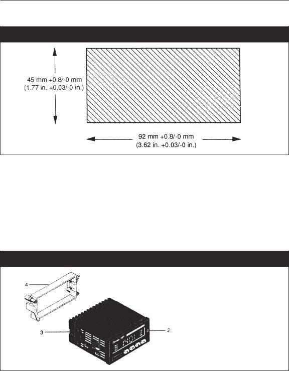
¥Prepare panel cutout to dimensions shown here.
¥Remove instrument from case with front panel screw.
¥Slide rubber gasket over case.
¥Slide case through cutout and slide mounting frame over case rear, engaging the detents in the case. Use a screwdriver to snug the mounting frame to the panel.
2.WIRING
¥Connect wires from cable to terminals as indicated in diagram
¥Connect AC power as indicated in diagram.
¥If applicable, connect alarm(s). Note that alarm defaults are High, Reverse Acting.

4
3.SCALING
¥Insert instrument in case and tighten screw.
¥Display will indicate 1290 then CONF.
¥Push F key three times. Display will read F.S.U. (Full Scale Value).
¥Using the Down arrow key, select the value that matches the full scale of the transducer. Enter with F key. (If your transducer is 10,000 PSI, no adjustment is necessary.)
¥Remove instrument from case and close mode selection switch as shown.
¥Reinsert instrument into case and tighten screw.
4.CALIBRATION AND OPERATION
¥When power is applied, display will read 1290 then a Pressure reading. At this point, be sure that no pressure is applied and that the transducer is at operating temperature.
¥Press the F key and the legend LO. OFF appears. Using the Up arrow key, advance the legend to LO.ON.
¥Press the F key to initiate zero calibration. After approximately 5 seconds, the legend F.U.S.C. will appear and alternate with the
¥Press the Up arrow key to advance to the legend FU ON. using the F key, initiate the
¥The system is now ready for use.
1290 Strain Gage Input Indicator |
5 |
1.INDICATOR DESCRIPTION
The Dynisco Model 1290 Strain Gauge Input Indicator is a flexible, programmable indicator designed for 350 ohm strain gauge based sensors, such as pressure transducers and load cells. The five digit, 0.52Ó LED display provides a precise, readable indication of the measured value.
You can program the 1290 to display in engineering units up to a full scale value (fsv) of 99,900 with an accuracy of ± 0.1%. The span value, alarm set points and other constants are stored indefinitely in
Two independent SPST alarm relays are another available feature of the 1290. The dual high or low set points are easily programmed from the front keyboard and are displayed on the digital display. The low alarms can be set up as
A programmable voltage or current retransmission output is available as an option. You can select a voltage output of
The Model 1290 can also be supplied with bidirectional and half duplex
Other features of the 1290 are:
¥A peak reading display (high and low) selected from the front panel
¥A digital filter to reduce the effects of input variations on the display, analog output and alarms
¥Input interruption sensing to detect when a transducer or any one of its leads has been disconnected
¥A program lockout feature that disables the front keyboard to prevent un authorized or accidental changes
¥An input signal that can be configured for either resetting the alarms or triggering
¥A digital display that provides operator prompts with messages to show current status or errors
¥A compact, 48mm by 96mm (1.89in. x 3.78 in.), 1/8 DIN enclosure that projects only 144mm (5.67 in.) behind the panel

6
2.SPECIFICATIONS
2.1 |
GENERAL |
|
Case |
|
PC/ABS, Black |
|
|
|
Dimensions |
48 mm high x 96 mm wide x 144 mm deep |
|
|
|
(1.89 in. high x 3.78 in. wide x 5.67 in. deep) |
|
|
1/8 DIN per DIN 43700 |
Installation |
Panel mounted, secured by mounting frame |
|
|
45 mm high x 92 mm wide, +0.8 |
|
|
|
(1.77 in. high x 3.62 in. wide, +0.03 |
Front panel |
IP 65 protection per IEC 569/CEI |
|
Rear terminal block |
22 screw terminals with safety cover |
|
Display |
|
5 red LED digits, 13.2 mm high |
|
|
7 segments plus decimal point |
Indicators |
2 red LEDs for alarm annunciator function |
|
|
|
1 red LED for local/remote control |
Keyboard |
Four pushbuttons |
|
Sampling time |
100 ms typical |
|
Display update time |
400 ms |
|
Common mode rejection ratio |
120 dB @ 50/60 Hz |
|
Accuracy |
± 0.1% fsv ±1 digit @ 25°C |
|
Temperature drift |
Less than 200ppm/°C of fsv |
|
Insulation resistance |
Greater than 100 Mohm, per IEC 348 |
|
Dielectric strength |
1500 V rms, per IEC 348 |
|
Power supply |
Switching 85/264 VAC, 50/60 Hz |
|
|
|
(24 VDC ± 10% factory order option) |
1290 Strain Gage Input Indicator |
7 |
Power consumption |
100 mA @ 110 VAC maximum |
Protection |
Internal thermistor |
Normal mode |
60 dB @ 50/60 Hz |
Weight |
600g |
Operating temperature |
0 to 50°C |
Storage temperature |
|
Humidity |
85% relative humidity, |
2.2STRAIN GAUGE INPUT
Input |
350 ohm bridge |
Bridge excitation |
10 V +7% |
Bridge sensitivity |
2 to 4 mV/V |
Input signal |
|
Calibration |
With or without shunt resistor |
Shunt value |
From 40.0% to 100.0% |
Zero balance |
± 25% of fsv |
Tare |
± 25% of fsv |
Readout |
Keyboard programmable from 10 to 99900 |
Input resolution |
Adjustable by 1 up to 2010 |
|
Adjustable by 10 from 2010 to 20100 |
|
Adjustable by 100 from 20100 to 99900 |
|
Decimal point may be set in any position |
Open input detection |
On any one of the 4 transducer leads, selectable up or down scale |
|
fault mode. |

8
2.3SPECIAL FEATURES
Display filter |
First order digital filter on displayed value, with configurable time |
|
constant of 0.4, 1, 2, 3, 4 or 5 seconds |
Peak detection |
Automatic detection of maximum and minimum measured value |
Input logic |
Driven by dry contacts for manual alarm reset or for |
Watch dog |
Hardware and software for automatic restart |
Protection |
Internal jumper for calibration and configuration |
|
Parameter protection |
|
Keyboard lockout |
2.4ALARMS
Quantity |
Two independent alarms |
Threshold |
0% to 100% of readout span |
|
Resolution and decimal point position as selected per readout |
|
value |
Hysteresis |
Programmable, 0.1% to 9.9% of readout span |
Type of alarms |
High or low thresholds |
|
Direct or reverse (failsafe) action |
|
Automatic or manual reset |
|
Optional low alarm startup masking |
Alarm output |
Two contacts, SPST, NO or NC, jumper selectable |
Update time |
100 ms |
Contact rating |
0.6A at 110 Vac resistive load; 0.5A at 220 Vac resistive load; 0.3A |
|
at 110 Vdc inductive load |
Filter |
Optional digital filter with the same time constant chosen for |
|
display filter |
2.5SERIAL COMMUNICATION INTERFACE (OPTION)
Type |
|
Protocol |
Polling/Selecting, modbUS, jbUS |
1290 Strain Gage Input Indicator |
9 |
Baud rate |
From 150 to 19200 baud |
Format |
7 bits + parity |
|
8 bits + parity |
|
8 bits without parity |
Parity |
Even/Odd |
Stop bit |
One |
2.6ANALOG RETRANSMISSION (OPTION)
Output types |
|
|
|
|
Keyboard and jumper selectable |
|
|
Scaling |
From 0 to 99900 |
|
Resolution and decimal point position are as selected per readout |
|
value |
Output resolution |
Better than 0.05% of output span (scaling can worsen output |
|
resolution) |
Filter |
It is possible to enable a digital filter on the output with the same |
|
time constant selected for the display filter |
Accuracy |
0.2% of output span |
Temperature drift |
Less than 100ppm/°C (plus input drift) |
Output noise |
Less than 0.1% fsv RMS |
Update time |
100 ms |
NOTE: The analog retransmission and serial communication interfaces are mutually exclusive.
3.INSTALLATION
3.1UNPACKING
Inspect the package for shipping damage. If you notice any damage, notify the freight carrier immediately.
10
3.2MOUNTING
Fig. 1 Panel Cutout
¥Make the instrument panel
¥Undo the screw (2).
¥Remove the unit from the instrument case (3).
¥Slide the gasket onto the instrument case (3).
¥Slide the the instrument case (3) through the
¥Slide the mounting frame (4) from the rear over the instrument case (3) so that the
¥Use a screwdriver to snug the mounting frame (4) and the instrument case (3).
¥Slide the instrument from the front into the instrument case (3).
¥Secure the instrument in the case with the screw (2).
Fig. 2 Side View, Mounting
1290 Strain Gage Input Indicator |
11 |
4.SETUP
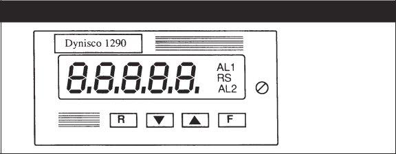
4.1FRONT PANEL
The front of the Model 1290 is shown in Figure 3. Key items on the front panel are:
¥A five digit LED display
¥LED indicators AL1 (Alarm 1) and AL2 (Alarm 2)
¥LED indicator RS (Remote Status)
¥Four pushbuttons protected by silicone rubber, labeled R, ▼, ▲, F. The pushbutton functions are listed in the table below.
Fig. 3 Front Panel
4.2PUSHBUTTON FUNCTIONS
Button Sequence |
Resulting Operation |
▼ |
Used to step between choices or to decrement a parameter value |
|
|
▲ |
Used to step between choices, increment a parameter value or to |
|
display peak high or peak low |
|
|
F |
Used to store currently displayed parameter value, |
|
as modified, and to display the next parameter |
R |
Used to scroll back to the previous parameter without storing the |
|
modified parameter value |
|
|
R + ▼ or |
Alarm manual reset (either button sequence will |
R + ▲ |
reset both alarms) |
|
|
R + F |
Reset peak high and peak low values |
|
|
▼ + ▲ |
Initiate default data loading procedure |
▼ + R + F |
Used to lock or unlock keyboard for transducer calibration |
|
and parameter modification |
12
To perform operations requiring two or more pushbuttons, press and hold the first pushbutton then press and hold the second pushbutton, and then press the third pushbutton, if required.
NOTE: You must follow the pushbutton sequences exactly as described.
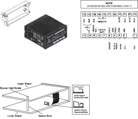
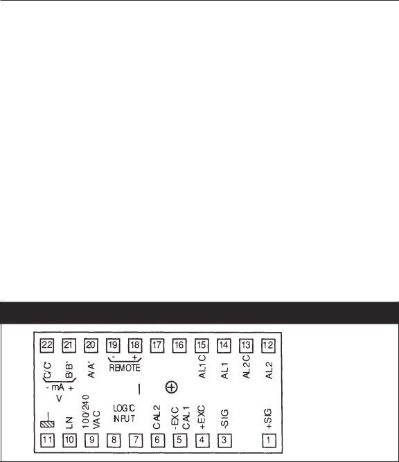
4.3REAR TERMINAL CONNECTIONS
The electrical connections for the Model 1290 are shown in the table below. The layout of the terminals, as seen from the rear, is shown in Figure 4.
Terminal |
Connection |
|
Dynisco Wire |
|
Terminal |
Connection |
|
|
1 |
Signal + |
|
Red |
|
12 |
Alarm 2 |
|
|
|
|
|
|
|
|
|
|
|
|
(no terminal) |
|
|
|
13 |
Alarm 2C |
|
|
3 |
Signal Ñ |
|
Black |
|
14 |
Alarm 1 |
|
|
|
|
|
|
|
|
|
|
|
4 |
+ Excitation |
|
White |
|
15 |
Alarm 1C |
|
|
|
|
|
|
|
|
|
|
|
5 |
Ñ Excitation/ CAL1 |
|
Green + Blue |
|
16 |
N/C |
|
|
6 |
CAL 2 |
|
Orange |
|
17 |
N/C |
|
|
|
|
|
|
|
|
|
|
|
7 |
Logic Input |
|
|
18 |
Remote Enable |
|
||
|
|
|
|
|
|
|
|
|
8 |
Logic Input |
|
|
19 |
Remote Enable |
|
||
9 |
Line (Hot side) VAC, or +24 VDC |
|
20 |
|
|
A/AÕ |
||
|
|
|
|
|
|
|
|
|
10 |
Line (Neutral), or 0 VDC |
|
|
21 Output |
V/mA+ |
|
B/BÕ |
|
|
|
|
|
|
|
|
|
|
11 |
Ground |
|
|
22 Output |
V/mA- |
|
C/CÕ |
|
NOTE: Do not connect any wires to terminals 16 and 17.
Fig. 4 Rear Terminal Locations
4.4INPUT WIRING
Connect the pressure transducer per the instructions detailed below. Do not run input wires in the
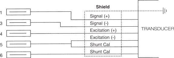
1290 Strain Gage Input Indicator |
13 |
same bundle with power cables; instead, shielded cable should be used and grounded at the transducer end only (DyniscoÕs cable assembly provides this grounding).
Dynisco Standard Wire Code |
Transducer |
|
|
Lead |
Color |
PT420 Series |
PT460 Series |
|
|
|
|
Excitation + |
White |
A |
C |
Signal + |
Red |
B |
A |
|
|
|
|
Excitation - |
Green |
C |
D |
|
|
|
|
Signal - |
Black |
D |
B |
Calibration |
Blue |
E |
E |
|
|
|
|
Calibration |
Orange |
F |
F |
|
|
|
|
|
|
G (unused) |
|
|
|
H (unused) |
|
4.5INTERNAL SETTINGS
The indicator consists of an upper and a lower printed circuit board and a front panel. These are connected by ribbon cables which are soldered in place.
CAUTION: Be careful not to twist the ribbon cables during assembly and disassembly.
4.5.1DISASSEMBLY
1.With a small slotted screwdriver, loosen the captive screw on the right side of the front panel.
2.Slide out the front panel and printed circuit board assembly, and place it on a flat,
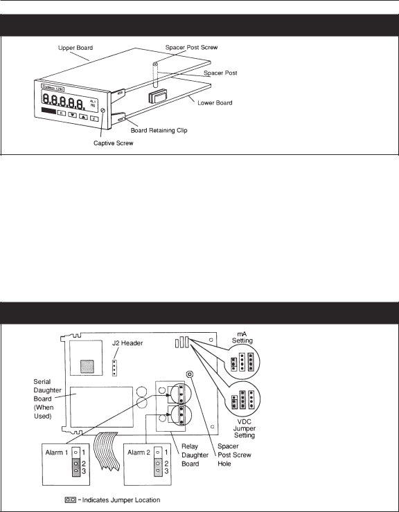
14
Fig. 5 Front Panel and Circuit Board Assembly
4.5.2OUTPUT JUMPER SETTINGS
Output options are selected by the placement of jumpers on the upper circuit board. The choices available are:
¥Voltage or current loop output for analog retransmission. Jumper setups are shown in Figure 6. The default selection is a
¥The alarm jumpers (normally open or normally closed) are shown in Figure 6 and described in the table on the next page. Each alarm is configured independently.
CAUTION: Wear an
Fig. 6 Upper Circuit Board and Jumper Settings

1290 Strain Gage Input Indicator |
15 |
The table below describes the alarm contact status based on the alarm jumper settings as selected from Figure 6 and the state of the Alarm Action settings as described in G1 and H on page 18.
Alarm Action |
Alarm Jumper |
Contact Status |
|
Reverse (fail safe) |
(NO) |
Contacts open in alarm or power loss |
|
|
|
|
|
Direct |
(NO) |
Contacts closed in alarm |
|
Reverse (fail safe) |
(NC) |
Contacts closed in alarm or power loss |
|
|
|
|
|
Direct |
(NC) |
Contacts open in alarm |
|
4.5.3MODE SELECTION
The Mode Selection Switch determines whether the indicator will be in configuration/calibration mode or the normal operating mode.
NOTE: The Configuration/Calibration Mode is only used when the indicator is first installed, or when reconfiguration of the indicator is required. At all other times, the operating mode is used.
Fig. 7 Model 1290 Side View, Mode Selection Switch
To access the Mode Selection Switch slide out the front panel and printed circuit board assembly, as instructed by steps 1 and 2 of Disassembly on page 13. Then, refer to Figure 7 to locate the switch and change the setting. Once the switch is set, refer to the following Reassembly procedure.
4.5.4REASSEMBLY
To reassemble the Model 1290, follow the steps below.
1.Slide the front panel and printed circuit board assembly into the instrument case and press it in so that the printed circuit board contacts mate with th terminal block in the back of the case. Tighten the front panel captive screw.
2.Perform configuration as outlined on the following page to ensure proper indicator setup and operation.

16
4.6CONFIGURATION/CALIBRATION MODE
The configuration/calibration mode is enabled by opening the Mode Selection Switch on the left side of the lower board (see Figure 7). A list of all configurable parameters starts below.
When the unit is turned on in configuration/calibration mode, the display will show 1290 and then
COnF.
Press F to initiate the configuration procedure, starting at the first parameter. Press R to initiate the configuration procedure, starting at the last parameter.
Press ▲ to toggle the display from COnF to CAL, initiating output calibration mode, if required. Pressing ▼ will display the software version number.
For each parameter you will either select one of several choices or enter a numerical value.
Press ▲ to modify or change the parameter or increase the number displayed. Press ▼ to modify or change the parameter or decrease the number displayed. Press F to save your changes and step to the next parameter.
Press R to step to the previous parameter without saving your changes.
For many parameter settings, the display initially alternates between a code and a numerical value. Once you start to modify the value, however, only the numerical value will be shown.
When entering a numerical value, ▲ and ▼ are used to increase or decrease the number being entered. The change in value for each step is either 1, 10, or 100, depending on the size of the number. The increment is 1 for values up to 2010, 10 from 2010 to 20100, 100 from 20100 to 99900.
4.7CONFIGURABLE PARAMETERS
The following is the complete sequence of configurable parameters. Default values are given on page 24.
A. LINE FREQUENCY
The display shows L.F. (Line Frequency) followed by: 60 for 60 Hz, or
50 for 50 Hz
B.DECIMAL POINT POSITION
The display shows:
-----for no digits after decimal point
1290 Strain Gage Input Indicator |
17 |
B1. FULL SCALE READOUT
The display alternates between F.S.U. (Full Scale Value) and a numerical value from 10 to 99900. Only the numerical value will be shown during modification., This value MUST be set equal to the sensor full range, e.g. 10,000 PSI.
C. DISPLAY FILTER TIME CONSTANT
The display shows F.T.C. (Filter Time Constant) followed by:
.4 for 400 millisecond filter time constant
1 for 1 second filter time constant
2 for 2 second filter time constant
3 for 3 second filter time constant
4 for 4 second filter time constant
5 for 5 second filter time constant
D. INPUT INTERRUPT
The display shows I.F.S. (Input Fail Safe) followed by:
Hi for up scale fail mode, or
Lo for down scale fail mode.
E.SHUNT CALIBRATION
The display shows S.C. (Shunt Calibration) followed by:
On for shunt calibration enabled, or
OFF for shunt calibration disabled.
NOTE: Set Shunt Calibrations to On when using Dynisco transducers.
E1. SHUNT CALIBRATION VALUE
This step is skipped if the shunt calibration is OFF.
The display alternately shows Shunt and a numerical value from 40.0 to 100.0, but only the numerical value will be shown during modification. This value corresponds to the percentage of the Full Scale Value.
NOTE: When using Dynisco transducers, the Shunt Calibration value should be set to 80.0
F.EXTERNAL CONTACT function
The display shows E.C. (External Contact) followed by:
nr to enable external contact for manual alarm reset, via rear terminals 7 and 8, or Ho to enable external contact for
F1. CONTACT STATUS
The display shows C.S. (Contact Status) followed by:
CL if function selected above is performed with contact closed, or
OP if function selected above is performed with contact open.

18
G. ALARM 1 OPERATIVE MODE
The display shows A1 (Alarm 1) followed by:
HA High alarm with automatic reset
HL High alarm with manual reset (High Latched Alarm)
LA Low alarm with automatic reset
LLLow alarm with manual reset (Low Latched Alarm) OFF for no Alarm 1
G1. ALARM 1 ACTION
This step is skipped if Alarm 1 is OFF.
The display shows A1 (Alarm 1) followed by:
rEU for relay energized if no alarm condition (reverse action/fail safe), or dir for relay energized if alarm condition (direct action).
G2. ALARM 1 MASKING OPTION
This step is skipped if Alarm 1 is OFF or HIGH. The display shows A1 (Alarm 1) followed by:
dIS for masking option disabled, or Enb for masking option enabled.
This function masks low alarm conditions during startup until the measured value first becomes greater than the alarm threshold plus hysteresis. The alarm must have been programmed as a low alarm.
G3. ALARM 1 FILTER
This step is skipped if Alarm 1 is OFF.
The display shows F1 (Filter) followed by:
OFF for no filter on alarm threshold, or
xxxfor filter with the time constant chosen in step C above.
G4. ALARM 1 HYSTERESIS
This step is skipped if Alarm 1 is OFF.
The display shows H1 (Hysteresis 1) followed by a value from 0.1 to 9.9. This value corresponds to the percentage of the Full Scale Value.
H. ALARM 2
Follow the same procedure as in steps
I.SERIAL COMMUNICATIONS PROTOCOL NOTE: This step will default to:
OFF if unit does not have the Serial Communications Interface option. ErO if unit has the Serial Communications Interface option.
The device will support the following protocols: ErO for polling/selecting protocol
nbUS for Modbus protocol
1290 Strain Gage Input Indicator |
19 |
JbUS for Jbus protocol
OFF to disable comms
NOTE: This indicator skips steps I1 and I2 if serial communication is not implemented (set to OFF).
I1. SERIAL COMMUNICATION DEVICE ADDRESS
The display shows Adr (address) followed by a number ranging from:
I2. SERIAL COMMUNICATION BAUD RATE The display shows bd (baud rate) followed by:
150 for 150 baud
300 for 300 baud
600 for 600 baud
1.20for 1200 baud
2.40for 2400 baud
4.80for 4800 baud
9.60for 9600 baud
19.2for 19200 baud
I3. SERIAL COMMUNICATION BYTE FORMAT
The display shows bF (byte format) followed by: 7E for 7 bits with even parity
70 for 7 bits with odd parity
8E for 8 bits with even parity
80 for 8 bits with odd parity
8 for bits with no parity
NOTE: The indicator skips steps L to L3 if analog retransmission is implemented.
L.ANALOG RETRANSMISSION (Option)
The display shows A0 (Analog Output) followed by:
0.20for
4.20for
0.10for
OFF for retransmission disabled
L1. ANALOG RETRANSMISSION SCALING: LOW SCALE VALUE
The display alternately shows Ar. L.S.U. (Analog Retransmission Low Scale Value) and a numerical value. This parameter establishes the lower limit for the analog output; only the numerical value is shown during modification. Resolution and decimal point position are as selected for the readout value.

20
L2. ANALOG RETRANSMISSION SCALING: FULL SCALE VALUE
The display alternately shows Ar. F.S.U. (Analog Retransmission Full Scale Value) and a numerical value. This parameter establishes the upper limit for the analog output; only the numerical value is shown during modification. Resolution and decimal point position are as selected for the readout value.
L3. ANALOG RETRANSMISSION FILTER
The display shows rF followed by:
OFF for no filter on retransmitted value, or
xxxfor filter having the time constant chosen in step C. Press F to lock in the parameter.
At this point the configuration procedure is complete and the display will return to showing COnF.
If necessary, you may now select the analog output calibration procedure by pressing ▲. Refer to Analog Output Calibration, below.
When configuration/calibration is complete, remove the unit again, place the Mode Selection switch in the ÒnormalÓ (closed) position, and replace the unit. See Mode Selection, page 15.
Proceed to Operating Mode, page 21.
4.8ANALOG OUTPUT CALIBRATION
Press ▲ to toggle the display from COnF to CAL, initiating output calibration mode. Press ▼ to display the software version number.
Press F to initiate the calibration procedure, starting at the first parameter. Press R to initiate the calibration procedure, starting at the last parameter.
Perform the calibration procedure in accordance with the jumper settings to select:
¥Current Output, or
¥Voltage output.
The jumper locations for these output selections are shown in Figure 6. When the display shows CAL, you can also load the default parameters, shown on page 24.
To calibrate the analog retransmission output, connect a multimeter, set to the proper measurement range, to terminals 21 and 22. Press the F key to reach desired parameter then make output adjustments by pressing ▲ or ▼ until the signal output measured by the multimeter reaches the proper value. The display only shows the number of counts for the digital to analog converter.
C6 - Retransmission current output minimum value - adjust to 50.0 m∝
C7 - Retransmission current output maximum value - adjust to 20.0 MA
C8 - Retransmission voltage output minimum value - adjust to 0.00 VDC
C9 - Retransmission voltage output maximum value - adjust to 10.00 VDC
1290 Strain Gage Input Indicator |
21 |
After the last step , the calibration is complete. The display shows the measured input variable in bits (approximately 1.6 microvolt/bit).
NOTE: The above procedure only applies to indicators ordered with the output option. Units are precalibrated from the factory.
5.OPERATING MODE
In this mode the Model 1290 monitors the input signal, displays the measured value, and performs alarm functions. You can display high and low peak values, lock and unlock the keyboard, reset alarms, and perform transducer input calibration and alarm threshold settings. It is also possible to load default parameters.
Parameter values listed below can always be viewed, but they can only be modified if the indicator keyboard is unlocked. If anyone attempts to modify parameters when the indicator is locked, the display will show inh.
5.1KEYBOARD LOCK/UNLOCK
When the measured value is displayed (normal operating mode), you can lock or unlock the keyboard by holding down the buttons in the following order; ▼ + R + F. The display will then show the new desired mode: Loc or UnLoc.
5.2TRANSDUCER INPUT CALIBRATION
You can modify the operating parameters and load default data only when the instrument is unlocked and in local mode. Default values are shown on page 24.
NOTE:
1.Transducer/ Indicator calibration should be performed with the transducer at operating temperature, and with no pressure applied.
2.The Zero and Full scale calibrations should be done concurrently.
1.ZERO TRANSDUCER CALIBRATION
Press F to enter the calibration mode. The display will show LO.OFF.
Press the ▲ key once.
The display will show LO.On.
Press the F key to perform the zero calibration. The display will blank except for 5 decimal points.
After a brief Òtime outÓ the unit will enter full scale calibration.
NOTE: In lieu of the ▲ key, pressing the F key will advance the indicator to the next parameter.

22
2.FULL SCALE TRANSDUCER CALIBRATION
The display alternates between FU.S.C. and the value of full scale in engineering units. Press the ▲ key once.
The display shows FU on.
Press F to go to perform the full scale calibration.
The indicator automatically returns to operating mode after 6 seconds if no changes are made.
3.TARE CALIBRATION (weight applications only)
The display alternates shows tArE and the value of the tare in engineering units. The tare will be forced to zero whenever zero or full scale calibration is performed. At this point there are two options:
a.To perform calibration press ▲. The display shows tA. followed by:
OFF to disable calibration ON to enable calibration
b.If calibration is not needed, press F to go to the next parameter. The instrument automatically returns to operating mode after 6 seconds if no changes are made.
5.3ALARM SET POINTS
If the indicator has automatically returned to operating mode you can return to set the alarms by following the procedure.
1.Alarm 1
Press F four times. The display will alternately show 1.xxxx and the alarm set point where xxxx is a code for alarm operation mode. Only the alarm set point is shown during modification. Use the ▲ and ▼ keys to modify this parameter. Resolution and decimal point position are as selected for the readout value. Press F to store your change. The indicator automatically returns to the normal operating mode after 6 seconds if no changes are made.
The codes for the remaining digits in the alarm operating mode are:
2nd digit |
3rd digit |
4th digit |
5th digit |
H = High alarm |
A = Automatic reset |
d = Direct action |
n = Low alarm mask |
|
|
|
|
L = Low alarm |
n = Manual reset |
r = Reverse action |
blank = Not masked |
for example, a display of I.HAr would indicate High alarm, auto reset, reverse action.
2.Alarm 2
The indicator will automatically enter this parameter after the F key is pressed to store the Alarm 1 set point. To enter Alarm 2 from the normal operating mode, press F five times. Programming the Alarm 2 set point is the same as Alarm 1 above, except that the display alternately shows 2xxxx and the alarm value.
1290 Strain Gage Input Indicator |
23 |
5.4ALARM RESET FUNCTION
This function can be performed when the indicator is locked; must be in local mode. If the alarm is configured as a latched alarm (manual reset), alarm status is maintained even after the alarm condition stops.
Press R + either arrow (▲ or ▼) to reset both Alarm 1 and Alarm 2. The external contact, if enabled, resets both alarms. The rear terminal connections are 7 and 8. The external contact works even if the indicator is in remote mode.
5.5PEAK HOLD FUNCTION
The following actions can be performed when the indicator is locked, and in either local or remote mode.
a.Monitoring Peak High and Peak Low.
By pressing ▲ while the measured value is displayed, it is possible to monitor the peak high value. The decimal point at the right of the display will be lit steadily.
Press ▲ again to monitor the peak low value. The decimal point at the right of the display will now blink on and off.
Press ▲ to redisplay the measured value (normal operating mode).
Press R + F to reset the peak high/peak low values and to restart for a new peak detection.
b.
The external contact can be used to freeze input signal sampling, holding the last measured value for use on the display, alarms, retransmission, etc.
In this mode, the numerical value flashes on the display.
6.DEFAULT DATA LOADING PROCEDURE
In each one of the indicatorÕs three modes, configuration, calibration, and operation, you can load default data to reset all of the parameters for that particular mode.
To load the default data:
Press ▼ + ▲, and once the display shows dF OFF, press ▲ . When the display shows dF On press F. Default data will now be loaded. During data loading time the display will show L.dAtA.
The default data for the three modes are shown on the following pages.

24
6.1DEFAULT DATA FOR CONFIGURATION PARAMETERS
Parameter |
Description |
Setting |
A |
Line frequency |
60 Hz |
|
|
|
B |
Decimal point position |
None |
B1 |
Full scale readout |
10000 |
|
|
|
C |
Display filter time constant |
400 ms |
|
|
|
D |
Input Interrupt |
High |
E |
Shunt calibration |
Enable |
|
|
|
E1 |
Shunt calibration value |
80.0% |
|
|
|
F |
External contact function |
Alarm manual reset |
F1 |
Contact status |
Closure |
|
|
|
G |
Alarm 1 operating mode |
High with automatic reset |
|
|
|
G1 |
Alarm 1 action |
Reverse |
G2 |
Alarm 1 masking option |
Disable |
|
|
|
G3 |
Alarm 1 filter |
Off |
|
|
|
G4 |
Alarm 1 hysteresis |
1.0% |
H |
Alarm 2 operating mode |
High with automatic reset |
|
|
|
H1 |
Alarm 2 action |
Reverse |
|
|
|
H2 |
Alarm 2 masking option |
Disable |
H3 |
Alarm 2 filter |
Off |
|
|
|
H4 |
Alarm 2 hysteresis |
1.0% |
|
|
|
I |
Serial communiction type |
OFF (w/o RS485) ERO (w/ RS485) |
I1 |
Serial communication address |
1 |
|
|
|
I2 |
Serial communication Baud rate |
19200 |
|
|
|
I3 |
Serial communication byte format |
7 bit, parity even |
L |
Analog retransmission type |
0.00 (Disable) |
|
|
|
L1 |
Analog retrans. low scale value |
0.00 |
|
|
|
L2 |
Analog retrans. full scale value |
10000 |
L3 |
Analog retransmission filter |
Off |
6.2DEFAULT DATA FOR OPERATING PARAMETERS
Parameter |
Description |
Setting |
1 |
Zero transducer calibration |
0 mV |
2 |
Full scale transducer calibration |
33.3 mV |
|
|
|
3 |
Tare calibration |
0 mV |
|
|
|
4 |
Alarm 1 threshold setting |
40% of fsv |
5 |
Alarm 2 threshold setting |
60% of fsv |
|
|
|
6 |
Keyboard status |
Unlocked |
1290 Strain Gage Input Indicator |
25 |
6.3DEFAULT DATA FOR CALIBRATION PARAMETERS
Default calibration parameters are provided to allow the user to verify that the instrument is working properly. They are not normally used as the final calibration values.
CAUTION: After default parameter loading, you should perform the proper indicator calibration procedure.
7.ERROR MESSAGES
Diagnostics are performed at instrument startup and during normal mode operation. If a fault condition is detected, the display will show the message Er followed by an error code. The following is a list of possible errors in numerical order.
Er 1
The alarm threshold values or transducer calibration (tare or zero) are out of limits or their values in memory are incorrect. The error may appear at instrument startup in operating mode.
After 3 seconds, the instrument will reset. Simultaneously press ▼ and ▲ to load default data. Then load the desired threshold values and recalibrate the transducer.
Er 6
This error message appears during tare or zero transducer calibration if input value is greater than
±25% of full scale calibration. The same error message appears during full scale calibration if the stored zero calibration value is greater than ±25% of the new full scale calibration. In both cases the stored calibration value is not changed. This error message disappears automatically after 2 seconds.
Er 7
This error message appears during zero or full scale transducer calibration if a fault condition (hold-
Er 38
Error detected during EAROM read operation. This error may appear at instrument startup in operating mode. This error message disappears automatically after 3 seconds, and the instrument resets. If the error persists, return the instrument to your supplier.
If this error appears during configuration/calibration, press F or R to restart the procedure and then repeat operations. If the error persists, return the instrument to your supplier.

26
Er 39
Error detected during EAROM write operation. This error may appear in operating mode when storing a new value in EAROM (for example, alarm threshold or transducer calibration). the new values will be enabled but they will be lost when the instrument is powered down. This error message disappears automatically after 10 seconds.
If this error appears during configuration/calibration, press F or R to restart the procedure and then repeat operations. If the error persists, return the instrument to your supplier.
Er 101
The configuration data stored in EAROM is wrong or inconsistent. The error may appear at instrument startup in operating mode. This error message disappears automatically after 3 seconds, and the instrument resets.
If the error persists, enable configuration/calibration mode with the internal switch, load the default calibration data and then perform a new configuration.
Er 201
The calibration data stored in EAROM for analog retransmission is wrong. The error may appear at instrument startup in operating mode. This error message disappears automatically after 3 seconds, and the instrument resets.
If the error persists, enable configuration/calibration mode with the internal switch, load the default calibration data and then perform a new analog retransmission calibration.
Er 312
Error during internal autozero measurement for temperature drift compensation. The instrument repeats this check every 3 seconds. The analog retransmission and alarm go low scale or high scale as a failsafe configuration. If the error persists, return the instrument to your supplier.
Er 402
The configuration/calibration data stored in EAROM is not protected. The error may appear at instrument startup in operating mode. This error message disappears automatically after 3 seconds, and the instrument resets.
If the error persists, enable configuration/calibration mode with the internal switch, power up the unit and then return to operating mode. This action should be sufficient to enable data protection.
o o o o o
1290 Strain Gage Input Indicator |
27 |
This status is displayed when the A/D converter value is out of range, or the input signal is greater than full scale value plus 27% of span, or the displayed value exceeds the display capability of 99900.
- o o o o
This status is displayed when the A/D converter value is out of range, or the input signal is lower than low scale value minus 27% of span, or the displayed value exceeds the display capability of - 1990.
OPEn
This message is displayed when the instrument detects an input on any one of the four transducer leads.
8.REPAIR
Questions concerning warranty, repair cost, delivery, and requests for a RA# should be directed to the Dynisco Repair Department,
DYNISCO LLC
Attn: RA # _______________
38 Forge Parkway Franklin, MA 02038
For technical assistance please call
9.WARRANTY
This Dynisco product is warranted under terms and conditions set forth in the Dynisco Web Pages. Go to www.dynisco.com and click on ÒWarrantyÓ at the bottom of any page for complete details.
NOTES:

WARRANTY REGISTRATION CARD
MODEL NUMBER ______________________________________________________________
SERIAL NUMBER _______________________________________________________________
DATE PURCHASED _____________________________________________________________
PURCHASED FROM ____________________________________________________________
NAME _________________________________________________________________________
COMPANY ____________________________________________________________________
DIVISION ______________________________________________________________________
STREET ________________________________________________________________________
CITY _____________________________ STATE _____________ ZIP __________________
COUNTRY _____________________________________________________________________
TELEPHONE _____________________________ FAX ________________________________
My application is _______________________________________________________________
Is this your first purchase from Dynisco? |
YES __________ |
NO __________ |
How did you first hear of Dynisco? |
ADVERTISING ________ |
REP __________ |
PREVIOUS USE ___________ COLLEAGUE _____________ DIRECTORY ______________
I need further product information on ______________________________________________
I need application help on ________________________________________________________
Please send complete catalog _____________________________________________________
Tel.:
PLEASE FOLD AND STAPLE OR TAPE
Place
Stamp
Here
DYNISCO LLC
38 FORGE PARKWAY FRANKLIN, MA 02038
ATTN: MARKETING DEPT.

Visit us on the world wide web:
DyniscoLLC
38 Forge Parkway
Franklin, MA 02038
USA
Tel: +1 508 541 9400
Fax: +1 508 541 9436
Email: InfoInst@dynisco.com
Dynisco Extrusion
1291 19th St Ln NW
Hickory, NC 28601
Tel:
Fax:
Email: InfoExtr@dynisco.com
Dynisco Polymer Test
Westgate II
730 Hemlock Road
Morgantown, PA 19543
Sales & Service:
Tel:
Fax:
Email: InfoPT@dynisco.com
Dynisco Europe GmbH
WannenŠckerstra§e 24
74078 Heilbronn
Deutschland
Tel: +49 7131 2970
Fax:+49 7131 23260
Email: DyniscoEurope@dynisco.com
Dynisco Instruments S.a.r.l. 466, rue du MarchŽ Rollay 94500 Champigny sur Marne France
Tel: +33 1 4881 8459
Fax: +33 1 4881 8334
Email: DyniscoFrance@dynisco.com
Dynisco.s.r.l.
Via Adriatico, 2/2
20162 Milano
Italia
Tel: +39 02 661 01733
Fax: +39 02 661 02908
Email: DyniscoItaly@dynisco.com
Dynisco UK Ltd.
Silver Birches Business Park
Aston Road, Bromsgrove
Worcestershire B60 3EU
Great Britain
Tel: +44 1527 577077
Fax: +44 1527 577070
Email: DyniscoUK@dynisco.com
Dynisco SPOL, S.R.O. cp. 579
756 55 Dolni Becva Czech Republic
Tel: +42 0651 647228
Fax: +42 0651 647224
Email: Dynisco_cz@ova.pvtnet.cz
Dynisco B.V.
Muziekplein 67
PO Box 666
The Netherlands
Tel: +31 413 250665
Fax: +31 413 260548
Email:
Dynisco Spain
Edificio la Constructora C/Vallespir 24, Local No. 4
08970 Sant Joan Despi/ Barcelona
Tel: +34 934 77 65 20
Fax: +34 933 73 72 60
Email: DyniscoSpain@dynisco.com
www.dynisco.com