Form U 2A PDF Details

In the realm of manufacturing pressure vessels, thorough documentation and adherence to standards are paramount. One such pivotal document is the Form U-2A, known officially as the Manufacturer’s Partial Data Report (Alternative Form). This form plays a crucial role in the fabrication of pressure vessel parts by one manufacturer for another, under the stringent provisions of the ASME Boiler and Pressure Vessel Code Rules, specifically Section VIII, Division 1. It encases a myriad of details, starting from basic information such as the names and addresses of the manufacturer and purchaser, to intricate specifics of the pressure vessel part including type, material specifications, and various construction details like the shell, heads, and nozzles. Moreover, it covers essential compliance information, incorporating the ASME Code adherence, impact testing requirements, and hydrostatic, pneumatic, or combination test pressures. Crucially, the form also comprises certificates of shop or field compliance and inspection, signed by authorized representatives and inspectors, ensuring that the manufactured part meets the prescribed code standards. The Form U-2A, thereby, not only serves as a testament to the quality and code compliance of the vessel part but also facilitates a transparent communication channel between manufacturers, purchasers, and regulatory inspectors.

QuestionAnswer
Form NameForm U 2A
Form Length2 pages
Fillable?No
Fillable fields0
Avg. time to fill out30 sec
Other namesasme u2a form, form u 2a, asme form u 2a, u 2a

Form Preview Example

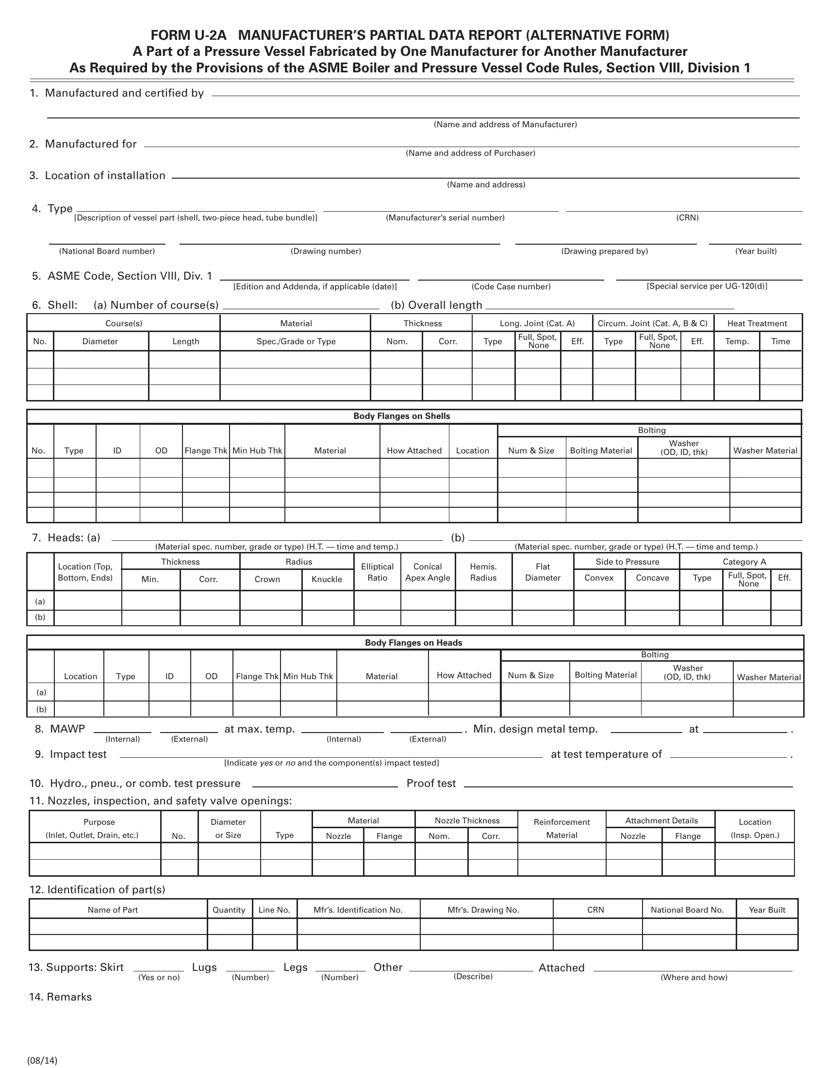
FORM U-2A MANUFACTURER’S PARTIAL DATA REPORT (ALTERNATIVE FORM)

A Part of a Pressure Vessel Fabricated by One Manufacturer for Another Manufacturer

As Required by the Provisions of the ASME Boiler and Pressure Vessel Code Rules, Section VIII, Division 1

1. Manufactured and certified by

(Name and address of Manufacturer)

2.

Manufactured for


(Name and address of Purchaser)


3.

Location of installation


(Name and address)


4.

Type


[Description of vessel part (shell, two-piece head, tube bundle)]


(Manufacturer’s serial number)


(CRN)


(National Board number)


(Drawing number)


(Drawing prepared by)


(Year built)

5.

ASME Code, Section VIII, Div. 1


[Edition and Addenda, if applicable (date)]


(Code Case number)


[Special service per UG-120(d)]


6.

Shell:

(a) Number of course(s)


(b) Overall length


Course(s)


Material


Thickness


Long. Joint (Cat. A)

Circum. Joint (Cat. A, B & C)

Heat Treatment


No.


Diameter


Length


Spec./Grade or Type


Nom.

Corr.

Type

Full, Spot,


Eff.


Type

Full, Spot,

Eff.

Temp.


Time


None


None


Body Flanges on Shells

No.

Type

ID

OD

Flange Thk Min Hub Thk

Material

How Attached

Location

Bolting

Num & Size

Bolting Material

Washer

Washer Material

(OD, ID, thk)


7.

Heads: (a)


(b)


(Material spec. number, grade or type) (H.T. — time and temp.)


(Material spec. number, grade or type) (H.T. — time and temp.)


Location (Top,


Thickness


Radius


Elliptical

Conical


Hemis.


Flat

Side to Pressure


Category A


Bottom, Ends)


Min.


Corr.


Crown

Knuckle


Ratio

Apex Angle


Radius


Diameter

Convex

Concave


Type

Full, Spot,

Eff.


None


(a)


(b)


Body Flanges on Heads


Bolting


How Attached

Num & Size


Bolting Material


Washer


Location


Type


ID


OD


Flange Thk

Min Hub Thk


Material


(OD, ID, thk)


Washer Material

(a)


(b)


8. MAWP


at max. temp.


. Min. design metal temp.


at


.


(Internal)


(External)

(Internal)


(External)


9.

Impact test


at test temperature of


.


[Indicate YES or NO and the component(s) impact tested]


10.

Hydro., pneu., or comb. test pressure


Proof test


11. Nozzles, inspection, and safety valve openings:


Purpose

(Inlet, Outlet, Drain, etc.)

No.

Diameter

or Size

Type

Material

Nozzle Thickness

Nozzle

Flange

Nom.

Corr.


Reinforcement

Material

Attachment Details

Nozzle

Flange


Location

(Insp. Open.)

12. Identification of part(s)

Name of Part

Quantity Line No.

Mfr’s. Identification No.

Mfr’s. Drawing No.

CRN

National Board No.

Year Built

13. Supports: Skirt


Lugs


Legs


Other


Attached


(Describe)


(Yes or no)

(Number)


(Number)


(Where and how)

14. Remarks


(08/14)

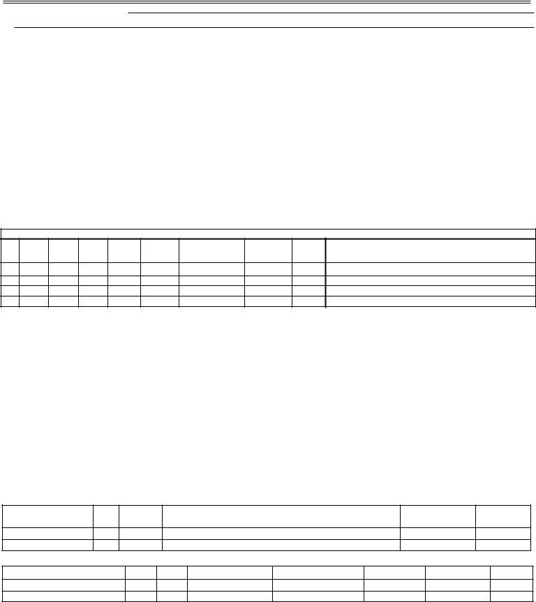
FORM U-2A (Back)

CERTIFICATE OF SHOP/FIELD COMPLIANCE

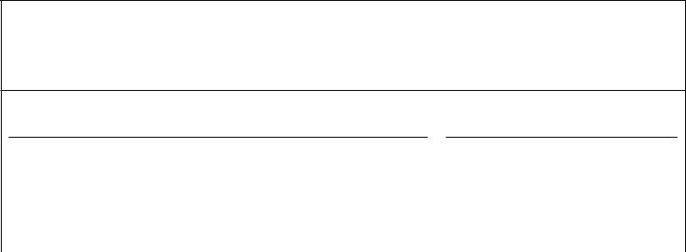
We certify that the statements made in this report are correct and that all details of material, construction, and workmanship of this pressure vessel part conform to the ASME BOILER AND PRESSURE VESSEL CODE, Section VIII, Division 1.

U Certificate of Authorization No.


Expires


Date


Name


Signed


(Manufacturer)


(Representative)

CERTIFICATE OF SHOP/FIELD INSPECTION

I, the undersigned, holding a valid commission issued by the National Board of Boiler and Pressure Vessel Inspectors and employed by of

have inspected the pressure vessel part described in this Manufacturer’s Data Report on

,


and state that, to the best of my knowledge and belief, the Manufacturer has constructed this pressure vessel part in accordance with ASME BOILER AND PRESSURE VESSEL CODE, Section VIII, Division 1. By signing this certificate neither the Inspector nor his/her employer makes any warranty, expressed or implied, concerning the pressure vessel part described in this Manufacturer's Data Report. Furthermore, neither the Inspector nor his/her employer shall be liable in any manner for any personal injury or property damage or a loss of any kind arising from or connected with this inspection.

Date


Signed


Commissions


(Authorized Inspector)

[National Board (incl. endorsements)]


(08/14)


How to Edit Form U 2A Online for Free

Working with PDF forms online is very easy using our PDF tool. You can fill out form u vfs global here within minutes. The editor is consistently improved by our team, acquiring new awesome functions and becoming greater. Here's what you will need to do to get started:

Step 1: Access the PDF doc inside our editor by pressing the "Get Form Button" at the top of this webpage.

Step 2: Once you open the tool, you will notice the document ready to be filled out. Apart from filling in various blanks, you might also do many other things with the file, including putting on any textual content, changing the initial text, adding graphics, signing the PDF, and more.

It really is simple to complete the form with this practical guide! This is what you must do:

1. You should complete the form u vfs global correctly, hence be mindful when working with the sections that contain these particular blank fields:
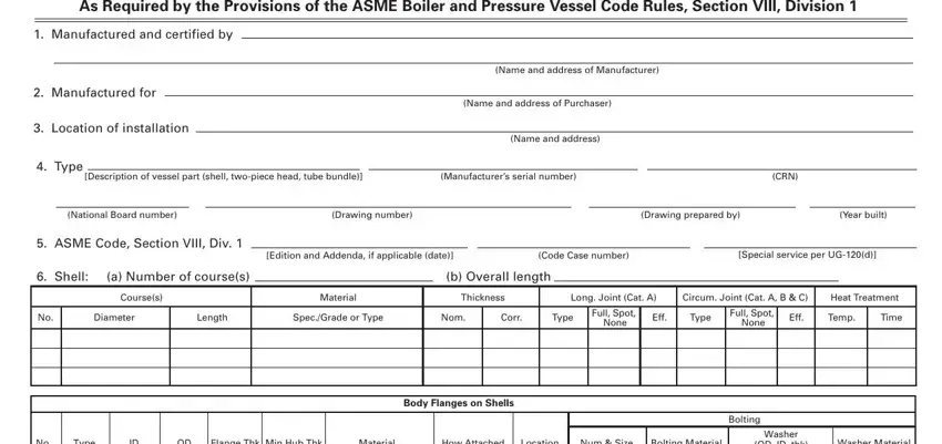
Guidelines on how to complete partial data report portion 1

2. Soon after filling in this section, go to the next step and fill out the essential details in these blank fields - Type, Flange Thk, Min Hub Thk, Material, How Attached, Location, Num Size, Bolting Material, OD ID thk, Washer Material, Heads a, Location Top Bottom Ends, Material spec number grade or type, Material spec number grade or type, and Thickness.
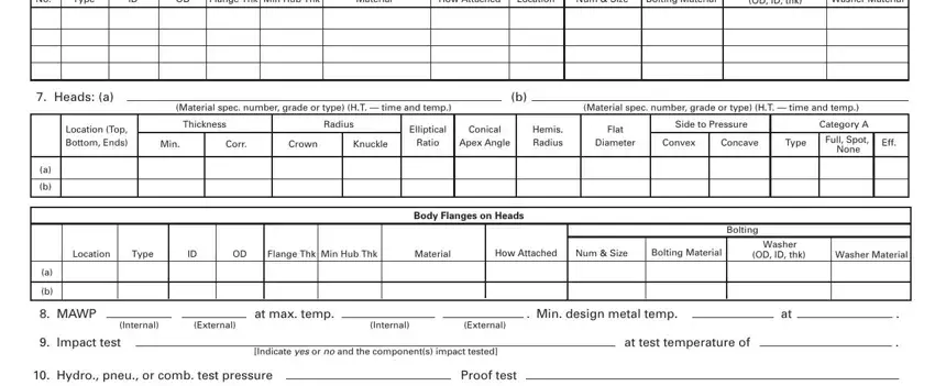
Stage number 2 of filling in partial data report

You can certainly make a mistake while filling out the Location, thus you'll want to look again prior to deciding to finalize the form.

3. Completing Purpose, Inlet Outlet Drain etc, Diameter, or Size, Type, Material, Nozzle Thickness, Reinforcement, Attachment Details, Nozzle, Flange, Nom, Corr, Material, and Nozzle is essential for the next step, make sure to fill them out in their entirety. Don't miss any details!

A way to complete partial data report stage 3

4. The form's fourth section comes next with the next few form blanks to complete: We certify that the statements, vessel part conform to the ASME, U Certificate of Authorization No, Expires, Date, Name, Signed, Manufacturer, Representative, CERTIFICATE OF SHOPFIELD INSPECTION, I the undersigned holding a valid, have inspected the pressure vessel, and state that to the best of my, ASME BOILER AND PRESSURE VESSEL, and makes any warranty expressed or.
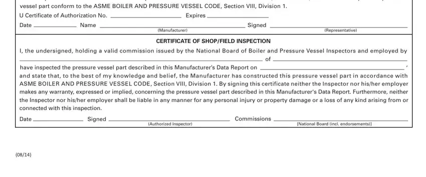
Filling in section 4 of partial data report

Step 3: Prior to moving forward, it's a good idea to ensure that form fields were filled out right. When you are satisfied with it, press “Done." Make a 7-day free trial subscription with us and get immediate access to form u vfs global - accessible inside your FormsPal cabinet. FormsPal guarantees protected form editing without data recording or distributing. Rest assured that your information is secure with us!