The Aisin AW 60-41SN transmission form, detailed within the AISIN AW 60-41SN (AF-17) Zip Kit installation and testing booklet, serves as a comprehensive guide for automotive professionals working on this specific transmission type. This form encompasses a variety of crucial information, including part number AW60-41SN-ZIP, torque specifications for numerous components like manual shaft detent, lever bolts, and transmission fluid cover bolts, as well as a fluid chart highlighting recommended capacities for Toyota and GM T-IV ATF. Additionally, it includes an insightful identification guide for valve bodies, indicating the 60-41SN (AF-17) valve body should utilize this kit due to its distinct characteristics like having a number 2 rear control body and a long TCC solenoid. Furthermore, the booklet elaborates on electronic cautions, detailing the transmission control module (TCM) programming and its impact on shifting behaviors such as economy and power modes, winter mode, neutral control, and hill hold, aiming to enhance performance based on driving conditions while possibly confusing drivers unfamiliar with these features. Installation instructions, solenoid apply charts, along with a meticulous rundown on valve body assembly, showcasing bolt length color charts and specific torque specifications, provide invaluable guidance. Critical wear areas and vacuum test locations are meticulously outlined, ensuring precise diagnostics and repairs of potential issues like shift complaints or pressure problems. The form not only acts as an essential toolkit for addressing the AW 60-41SN transmission but also as an educational resource, outlining proper installation techniques and troubleshooting methods to maintain optimal transmission performance.
| Question | Answer |
|---|---|
| Form Name | Aw60 41Sn Transmission Form |
| Form Length | 8 pages |
| Fillable? | No |
| Fillable fields | 0 |
| Avg. time to fill out | 2 min |
| Other names | manual de transmision aw6040 pdf, aw60 40le manual, aw60 40le pdf, aw60 41sn pdf |
AISIN AW
PART NUMBER |
INSTALLATION & TESTING BOOKLET |
Torque Specifications
Manual Shaft Detent |
Manual Shift Shaft Detent |
Spring Bolt |
Lever Bolts |
89 |
89 |
|
|
Manual Shift Shaft |
Park/Neutral Position |
Retaining Nut |
Switch Bolt |
61 |
18 |
|
|
Transmission Speed |
Torque Converter |
Sendor Bolt |
Housing Bolts |
48 |
22 |
|
|
Transmission Case |
Transmission Fluid |
Cover Bolts |
Bafle Bolts |
18 |
48 |
|
|
Transmission Fluid |
Transmission Fluid Pump |
Drain Plug |
Cover Bolt |
29 |
89 |
|
|
Transmission Fluid |
|
Bolts |
|
18 |
18 |
|
|
Fluid Chart
Recommended Capacities: Toyota / GM
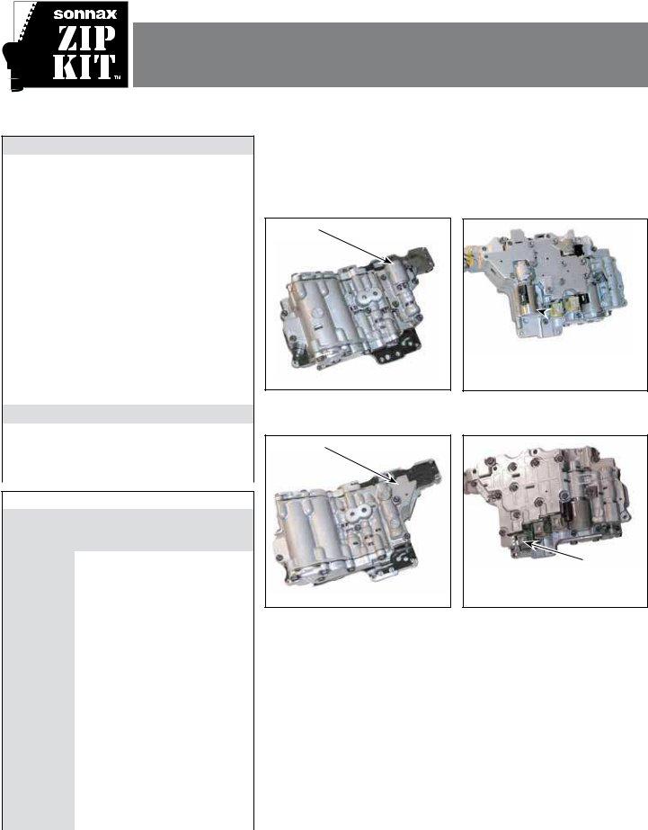
NOTE: This Zip Kit
Valve Body Identiication
Has a
Number 2
Rear Control
Body
Has a
Long TCC
Solenoid
Approximate Capacity, |
Approximate Capacity, |
Complete Overhaul |
Drain and Fill |
7.6 qt (7.2L) |
4.2 qt (4.0L) |
|
|
Component Apply Chart
|
|
|
|
Clutch |
|
Brake |
||||
|
Position |
|
|
Clutch |
||||||
|
|
|
|
|
|
|
||||
|
|
|
|
|
|
|
|
|
||
|
|
|
C0 |
C1 |
C2 |
C3 |
B1 |
B2 |
F0 |
F1 |
|
|
|
|
|
|
|
|
|
|
|
P |
|
|
|
|
|
X |
|
|
|
|
|
|
|
|
|
|
|
|
|
|
|
R |
< = 7 mph |
|
|
X |
X |
|
X |
|
|
|
|
|
|
|
|
|
|
|
|
|
|
R |
|
> 7 mph |
|
|
X |
X |
|
|
|
|
|
|
|
|
|
|
|
|
|
|
|
N |
|
|
|
|
|
X |
|
|
|
|
|
|
|
|
|
|
|
|
|
|
|
|
|
1 |
|
X |
|
X |
|
|
X |
X |
|
|
|
|
|
|
|
|
|
|
|
|
|
2 |
|
X |
|
X |
X |
|
X |
|
|
|
|
|
|
|
|
|
|
|
|
D |
|
N Cont. |
|
X |
|
X |
X |
|
X |
|
|
|
|
|
|
|
|
|
|
|
|
|
|
3 |
X |
X |
|
X |
|
|
X |
|
|
|
|
|
|
|
|
|
|
|
|
|
|
4 |
X |
X |
|
|
X |
|
|
|
|
|
|
|
|
|
|
|
|
|
|
|
|
1 |
|
X |
|
X |
|
|
X |
X |
|
|
|
|
|
|
|
|
|
|
|
3 |
|
2 |
|
X |
|
X |
X |
|
X |
|
|
|
|
|
|
|
|
|
|
|
|
|
3 |
X |
X |
|
X |
|
|
X |
|
|
|
|
|
|
|
|
|||||
|
|
|
|
|
|
|
|
|
|
|
|
|
4 |
X |
X |
|
|
X |
|
|
|
|
|
|
|
|
|
|
|
|
|
|
|
|
1 |
|
X |
|
X |
|
|
X |
X |
|
|
|
|
|
|
|
|
|
|
|
2 |
|
2 |
|
X |
|
X |
X |
|
X |
|
|
|
|
|
|
|
|
|
|
|
|
|
|
(3rd) |
X |
X |
|
X |
|
|
X |
|
|
|
|
|
|
|
|
|
|
|
|
1 |
|
1 |
|
X |
|
X |
|
X |
X |
X |
|
|
|
|
|
|
|
|
|
|
|
|
(2nd) |
|
X |
|
X |
X |
|
X |
|
|
|
|
|
|
|
|
|||||
|
|
|
|
|
|
|
|
|
|
|
No
Number 2
Rear Control
Body
Has a
Short TCC
Solenoid
©2012 Sonnax Industries, Inc. |
|
|
|
Page 1 |
Aisin AW
TIME TESTED • INDUSTRY TRUSTED
Electronic Cautions
performance Modes
he transmission control module (TCM) programming allows the driver to select among various modes for enhanced performance based upon driving conditions. he TCM itself has the capability to change modes automatically when speciic conditions are met. hese modes will alter shift feel, and could be confused with shift problems by the driver if they are unaware of the TCM programming.
•Economy Mode/Power Mode The transmission is programmed to start and operate in Economy Mode. This shift strategy sets the shift points to occur at a lower speed than Power Mode to maximize fuel economy. The TCM will automatically switch to Power Mode when the driver accelerates more aggressively (higher engine load), or at higher speed, maximizing performance.
•Winter Mode is activated by the driver by a switch on the shifter. This mode starts the vehicle in 3rd gear to reduce tire slip on icy/slippery roads. Once the vehicle is moving, the TCM will automatically shift to the appropriate gear. Shifting into manual 1st or 2nd will cancel Winter Mode.
•Neutral Control is automatically activated by the TCM if the vehicle is in Drive and comes to a stop for longer than 2 seconds with the brakes applied. This condition allows the C1 (forward clutch) to be disengaged, placing the vehicle in Neutral, for improved fuel economy. When the brake is released, the C1 clutch is automatically applied and the vehicle will take off in 1st gear.
•Hill Hold The TCM monitors vehicle speed to determine if the driver is coming to a stop on a hill. If so, the TCM will automatically apply the B1 (2/4 brake) to prevent vehicle rolling. Upon takeoff, the B1 brake is released, and the vehicle moves forward in 1st gear. The TCM will disable Neutral Control if Hill Hold is activated.
Installation & Testing Booklet
Solenoid Apply Chart
Solenoid
|
Position |
|
|
|
|
|
|
S1 |
S2 |
SN |
SLU |
||
|
|
|
||||
|
|
|
|
|
|
|
P |
|
|
X |
|
|
|
|
|
|
|
|
|
|
R |
< = 7 mph |
X |
|
|
|
|
|
|
|
|
|
|
|
R |
|
> 7 mph |
|
X |
|
|
|
|
|
|
|
|
|
N |
|
|
X |
|
|
|
|
|
|
|
|
|
|
|
|
1 |
X |
|
|
|
|
|
|
|
|
|
|
|
|
2 |
X |
X |
|
|
|
|
|
|
|
|
|
D |
|
N Cont. |
X |
X |
X |
|
|
|
|
|
|
|
|
|
|
3 |
|
X |
|
X |
|
|
|
|
|
|
|
|
|
4 |
|
|
|
X |
|
|
|
|
|
|
|
|
|
1 |
X |
|
|
|
|
|
|
|
|
|
|
|
|
2 |
X |
X |
|
|
3 |
|
|
|
|
|
|
|
3 |
|
X |
|
X |
|
|
|
|
|
|||
|
|
|
|
|
|
|
|
|
4 |
|
|
|
X |
|
|
|
|
|
|
|
|
|
1 |
X |
|
|
|
|
|
|
|
|
|
|
2 |
|
2 |
X |
X |
|
|
|
|
|
|
|
|
|
|
|
(3rd) |
|
X |
|
X |
|
|
|
|
|
|
|
|
|
1 |
X |
|
|
|
1 |
|
|
|
|
|
|
|
(2nd) |
X |
X |
|
|
|
|
|
|
|
|||
|
|
|
|
|
|
|
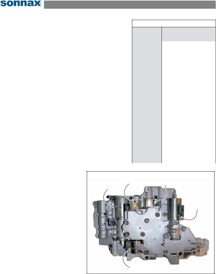
Solenoids
his
•The S1 solenoid is an on/off style, operated by the TCM to control the
•The S2 solenoid is an on/off style, operated by the TCM to control the
•The SN solenoid is an on/off style, operated by the TCM to operate Neutral Control.
•The SLU linear solenoid is pulse width modulated by the TCM to operate the converter clutch.
•The SLT linear solenoid is modulated by the TCM to regulate line pressure.
|
|
S1 Solenoid |
|
S2 Solenoid |
|
|
Figure 1 |
|
|
|
|
|
|||||
SLT Solenoid |
|
|
|
|
|
|
||
|
|
|
|
|
|
|||
|
|
|
|
|
|
|
|
|
|
|
|
|
|
|
|
|
|
|
|
|
|
|
|
|
|
|
|
|
|
|
|
|
|
|
|
|
|
|
|
|
|
SLU Solenoid |
|
|
|
|
|
|
|
|
|
||
|
|
|
|
|
|
|
|
|
SN Solenoid |
|
Test all ive solenoids at 20˚C/68˚F. |
|
|
©2012 Sonnax Industries, Inc. |
|
|
|
Page 2 |
Aisin AW
Installation & Testing Booklet
TIME TESTED • INDUSTRY TRUSTED
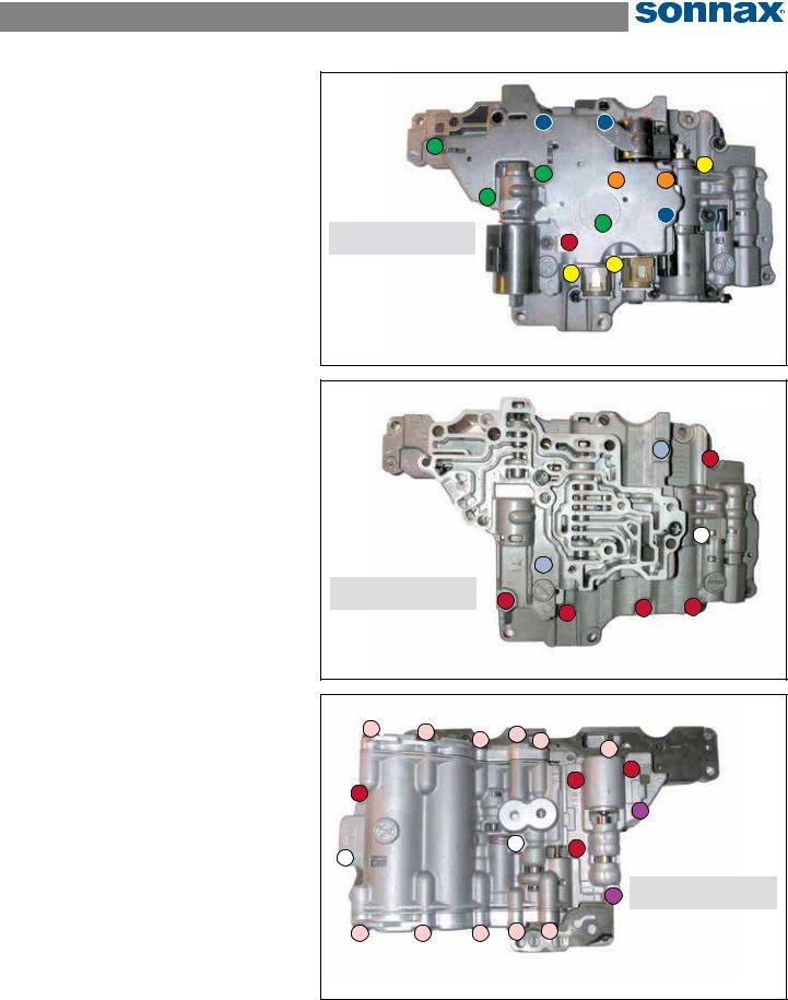
zip Kit Instructions
1. Valve Body Disassembly
NOTE: See color charts for bolt lengths.
a. Remove the 13 bolts (Figure 2).
b. Remove the ive solenoids (Figure 2).
c. Remove the eight bolts (Figure 3).
d. Remove the central
2. Installation
Install Zip Kit parts as shown on diagram of separate quick guide sheet included in this Zip Kit.
Bolt Color |
Bolt |
|
|
Code |
Length |
|
|
|
|
Yellow |
10mm |
|
Orange |
12mm |
|
Red |
16mm |
|
Green |
40mm |
|
Blue |
75mm |
|
|
|
Figure 2
Bolt installation torque speciications are 59
3.Valve Body Assembly
a.Loosely install the central
b.Loosely install the eight bolts (Figure 3), then torque to 59
c.Reinstall the ive solenoids (Figure 2).
d.Loosely install the 13 bolts (Figure 2), then torque to 59
Bolt Color |
Bolt |
|
|
Code |
Length |
|
|
|
|
Red |
16mm |
|
White |
38mm |
|
|
|
|
Lt Blue |
54mm |
|
|
|
Figure 3
Bolt installation torque speciications are 59
Bolt installation torque speciications are 59
Figure 4
Bolt Color |
Bolt |
|
|
Code |
Length |
|
|
|
|
Pink |
12mm |
|
Red |
16mm |
|
White |
38mm |
|
|
|
|
Purple |
50mm |
|
|
|
©2012 Sonnax Industries, Inc. |
|
|
|
Page 3 |
Aisin AW |
Installation & Testing Booklet |
TIME TESTED • INDUSTRY TRUSTED
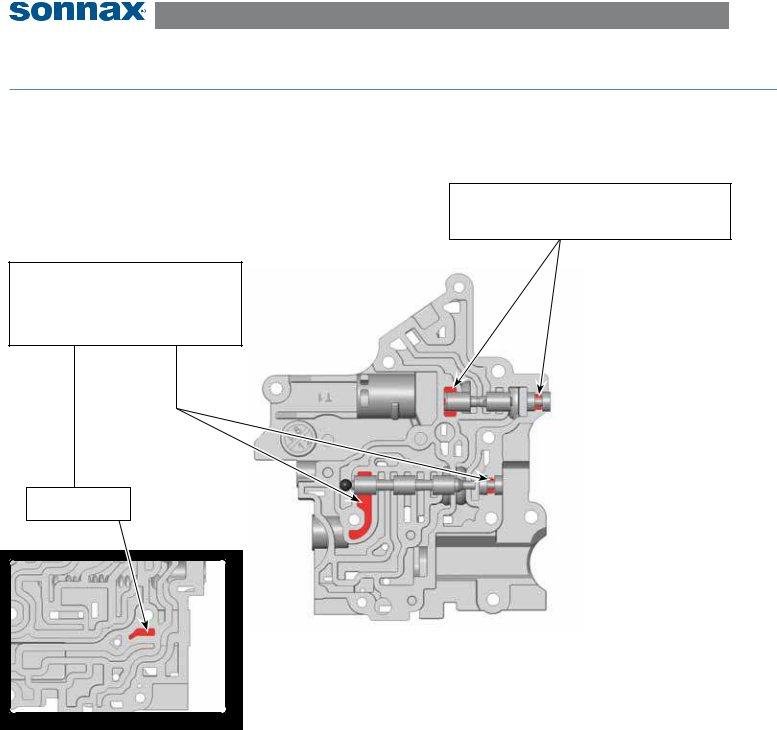
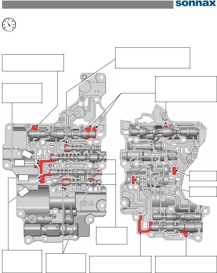
Critical Wear Areas & Vacuum test Locations
NOTE: OE valves are shown in rest position and should be tested in rest position unless otherwise indicated. Test locations are pointed to with an arrow. Springs are not shown for visual clarity. Low vacuum reading indicates wear.
Front Control Valve Body - top Side (Bottom Side Inset) Shown Here
Solenoid
Shift complaints in 2nd & 4th
NOTE: Invert valve (as shown) to test.
Neutral Relay Valve
•Delayed engagement
•Loss of neutral control feature
NOTE: Prop valve in outboard position with checkball and seal port on opposite side of casting.
Seal for neutral relay valve vacuum test.
Front Control Valve Body
Top Side
Front Control Valve Body
Bottom Side
©2012 Sonnax Industries, Inc. |
|
|
|
Page 4 |
Aisin AW
Installation & Testing Booklet
TIME TESTED • INDUSTRY TRUSTED
15
2010
25 5
300
VACUUM
TEST
Middle Control Valve Body - top & Bottom Sides Shown Here
Reverse Boost Assembly
•Low reverse pressure
•Delayed reverse
NOTE: Seal solenoid port when testing.
Test
Middle Control Valve Body
Top Side
Lockup Control Solenoid Valve
•Converter slip/shudder/codes
•No converter apply
NOTE: Test port by using
pressure Regulator Valve
•Low/High line pressure
•Soft/harsh shifts
•Converter complaints
•Loss of lube
Middle Control Valve Body
Bottom Side
Seal
Seal
Test
NOTE: Seal solenoid port as well as port on opposite side of casting.
NOTE: Seal port on opposite side of casting.
Shift Valve
End plugs
Shift complaints
Solenoid
Shift complaints in 2nd & 4th
Seal for
Seal for
Solenoid
Shift complaints in 2nd & 4th
©2012 Sonnax Industries, Inc. |
|
|
|
Page 5 |