In the realm of temperature control, precision is paramount, and the Inkbird ITC-100 Manual form emerges as a comprehensive guide to mastering such precision. The manual astutely covers a range of imperative topics, including safety warnings that underscore the need for adherence to specifications for avoiding hazards like electric shock or fire. It delves into the product features, showcasing its compatibility with a variety of temperature sensors and its ability to operate across a wide temperature spectrum with remarkable accuracy. With a detailed exposition on technical parameters and models, the manual serves the double purpose of a straightforward guide for installation and a technical handbook for troubleshooting. It thoroughly explains the installation process through diagrams and wiring instructions, ensuring users can easily set up their temperature controllers. Furthermore, the operational instructions provide a clear roadmap to navigating the controller’s functionalities from basic setup to advanced features like self-tuning for optimal PID control parameters. This mixture of safety protocols, installation guidelines, precise control features, and troubleshooting advice encapsulates the essence of the Inkbird ITC-100 Manual, making it an indispensable resource for anyone looking to harness the sophisticated temperature control capabilities of the ITC-100 PID Temperature Controller.
| Question | Answer |
|---|---|
| Form Name | Inkbird Itc 100 Manual Form |
| Form Length | 9 pages |
| Fillable? | No |
| Fillable fields | 0 |
| Avg. time to fill out | 2 min 15 sec |
| Other names | inkbird itc 100 manuale italiano, inkbird itc 100 manual italiano, inkbird itc 100rh manuale italiano, itc 100vh manual |

User Manual
V1.0
Contents
Safety warning …………………………………………………………………………………………………………………………………2
Product features .………………………………………………………………………………………………………………………………2
1.Technical parameters …………………………………………….…………………………………………………………………………2
2.Models and specifications ..…………………………………………………………………………………………………………………2
3.Diagram and installing size …………………………………………………………………………………………………………………2
4.Wiring diagram ………………………………………………………………………………………………………………………………2
4.1Connecting sensors …….….……………………………………………………………………………………………………………3
4.1.1Thermocouple ………………………...………………………………………………………………………………………………3
4.1.2Dual lines PT100 sensor……….……..………………………………………………………………………………………………3
4.1.3RTD sensor……….……………………………...……………………………………………………………………………………3
4.2Power supply connection ……………..…………………………………………………………………………………………………3
4.3connection for control signal output ……………………………………………………………………………………………………3
4.4Connection for alarm control ……………………………………………………………………………………………………………3
5.Panel instruction ……………..………………………………………………………………………………………………………………3
6.Operation instruction ...………………………………………………………………………………………………………………………3
6.1Display status ……………..………………………………………………………………………………………………………………3
6.2View output value ………………………………...………………………………………………………………………………………3
6.3Automatic/Manual control switch ………………………………………………………………………………………………………3
6.4Value setting ……………...………………………………………………………………………………………………………………3
6.5Launch
6.6Workflow for setting …………………………………………………………………………………………………………………...…4
6.7Parameters setting ………………………………………………………………………………………………………………………4
6.8Parameters related to alarm output: “HiAL,LoAL,dHAL,dHAL,dF,ALP,CF” ……..……………….……………..……………………5
6.8.1Alarm parameters: HiAL,LoAL,dHAL,dHAL …………………………….……………………………………………………….…5
6.8.2Defining parameter for alarm ALP ………………………………………………………………………..………………………5
6.8.3Hysteresis Band dF …………………………………………………………………………………………………………………5
6.8.4Function parameter CF ……………………………………………………………………………………………………………..5
6.9Parameters related to input “Sn,diP,diL,diH,DL,Sc” …………………………………………………………………….……………5
6.9.1Sensor type input “Sn” …………………………………………………………………………………………………………...…5
6.9.2Decimal point position“diP” …………………………………………………………………………………………………………5
6.9.3Definition parameters "diH" and "diL" for linear input range …………………………..…………………………………………5
6.9.4Filtering parameter“dL”………………………………………………………………………………………………………………5
6.9.5Sensor Calibration“Sc”………………………………………………………………………………………………………………5
6.10Parameters related to control output“oPI,oPL,oPH,CtrL” …………………………………………………………………...………5
6.10.1Output mode parameters "oPI", "oPL" and "oPH" are used for limiting output …………………………………………..……5
6.10.2Adjustment mode parameter "CtrL" ………………………………………………………………………………………………6
6.11PID control parameters related to
6.11.16.11.1 Holding parameter "M50" …………………………………………………………………………………………………..6
6.11.2Rate parameter "P" ……………………………………………………………………………………….………………………6
6.11.3Hysteresis time "t"…………………………………………………………………………………………………………..………6
6.11.4Function parameter "CtL" ………………………………………………………………………………………………………….6
6.12Communication parameter “Addr、bAud” ……………………………………………………………………………………………6
6.13Field parameter "EP1 - EP8" ……………………..……………………………………………………………………………………7
6.14Permission for parameters “Loc”“LOC” ……………………………………………………………………………………………7
6.15Common faults and handling methods ……………………………………………………………………………….………………7
7 Wiring instruction ……………………………………………………………………………………………………………………………7
7.1Directly control load by the internal relay of the instrument ..…………………………………………………………………………7
7.2Control the load via external contactor …………………………………………………………………………………………...……7
7.3SSR control ……………………………….……………………………………………………………………………………………7
7.4Solenoid valve or relay control ………..………………………………………………………………………………………………8
7.5Control load via external contactor (24V) …………………………………………………………………………………………..…8
8.Field application example …………………………………………………………………………………………………………………..8
|
© 2015 Inkbird Inc. All rights reserved. |
1 |
■Safety warning
●It’s a must to use this product within its specification and using scope.
●When power on, do not connect, disassemble and touch terminals, as those may cause damage due to spark, malfunction or electric shock.
●No metal fragment, wire thread or metal dusts produced during installation are allowed to be inside the device, otherwise, there will be risk of electric shock, fire or malfunction.
●Please do not use this product in flammable and explosive locations, otherwise, there will be risk of damage caused by explosion.
●Never disassemble, refit and repair this product, or touch the inner components by yourself, otherwise, there will be risk of electric shock, spark or malfunction.
●If the replay was serving beyond its estimated lifetime, there will be risk of
contact fusion and burning. It’s a must to always pay attention to the using
environment of relay, and using the relay within its rated load and estimated lifetime. The estimated lifetime of the relay varies according to the output load and switching condition.
■Product features
●Panel size: DIN(48×48mm)
●Compatible with various temperature sensors (K, S, Wre, T, E, J, B, N, CU50, PT100)
●Wide control temperature range:
●Display and control accuracy: 0.1 ºC, high measuring precision: ±0.2%FS
●PID control mode with
●Adjustable digital filtering for reducing external interference
●Inbuilt switching power supply applicable for wide voltage range with low power consumption
1.Technical parameters
|
AC |
|
|
|
|
Rated Voltage |
AC/DC |
|
|
|
|
|
DC |
|
|
|
|
Working voltage |
85 to 100% of the rated voltage |
|
|
|
|
|
About 5VA (100V - 240VAC) |
|
|
|
|
Power |
About 4VA (12V - 24VAC) |
|
|
|
|
|
About 3W (12V - 24VDC) |
|
|
|
|
|
PV: high luminance LED screen with 4 digits of height |
|
|
9.9mm displayed in red |
|
Characters |
|
|
SV: high luminance LED screen with 4 digits of height |
||
|
||
|
8.0mm displayed in green |
|
|
|
|
Display accuracy |
±0.2%FS 0.1ºC(<1000ºC); 1ºC(≥1000ºC) |
|
|
|
|
Sampling period |
0.5 seconds |
|
|
|
|
Temperature |
||
compensation |
||
|
||
|
|
|
|
Relay output: AC 250V 3A (resistive load) |
|
|
|
|
Control output |
Voltage output (for driving SSR): 12VDC, 30mA DC |
|
|
||
Maximum load: 600Ω |
||
|
||
|
|
|
|
Electrical endurance of relay: 100,000 times |
|
|
|
|
Alarm output |
Relay output: AC 250V 3A (resistive load) |
|
|
||
Relay output: AC 250V 3A (resistive load) |
||
|
||
|
|
|
Weight |
About 140g |
|
|
|
|
Working temperature |
||
|
|
|
Working humidity |
RH |
|
|
|
|
Storing temperature |
||
|
|
2.Models and specifications
Table 1: Product models and specifications
Model |
Control output |
Voltage |
|
|
|
SSR control output |
AC |
|
|
|
|
Relay control output |
AC |
|
|
|
|
SSR control output |
AC/DC |
|
|
|
|
Relay control output |
AC/DC |
|
|
|
|
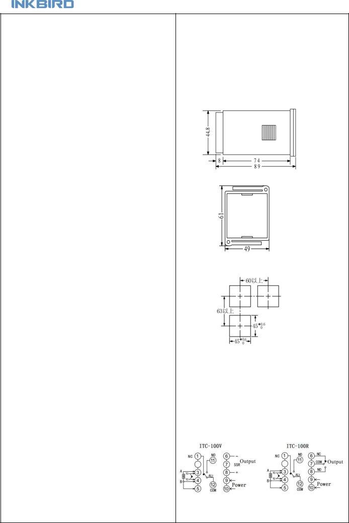
3.Diagram and installing size (unit: mm)
Figure 1: Shell Size
Figure 2: Mounting Bracket
Figure 3: Panel Cutout
3.1Insert temperature controller into the mounting hole in the panel, then put on the fixer from the rear and hold it temporarily, make sure there is no gap among temperature controller, panel and fixer. After that, fix the temperature controller with attached two bolts of the fixer under torque of 0.29N to 0.39N.
3.2Make sure the surrounding temperature is within the stipulated temperature range, especially when there are two or more temperature
controllers.
4.Wiring diagram
Figure 4:Wiring diagram
|
© 2015 Inkbird Inc. All rights reserved. |
2 |
4.1 Connecting sensors
Please refer to the input sensor reference table to select sensor type and set the code. The default setting of sensor type is type K thermocouple. If other type
sensor was adopted, it’s a must to reset the configuration.
If error occurred when some thermocouples are used in different environments, press SC to calibrate as per the detailed stipulation in this manual.
4.1.1 Thermocouple
#3 and #4 terminals are for connecting thermocouple. No inverse connection of positive pole and negative pole are allowed. For common thermocouples, positive pole is red, while negative pole is blue or green. If the poles were connected inversely, the measured value will be displayed inversely on the screen.
4.1.2 Dual lines PT100 sensor
#3 and #4 terminals are the input ports for dual lines PT100 sensor, at the same time #4 and #5 terminals should be connected together.
4.1.3 RTD sensor
When connecting three lines RTD sensor, #3 terminal is for red wire, #4 and #5 are for other two blue lines. For some sensors, #4 and #5 terminals should be connected together.
4.2 Power supply connection
#9 and #10 terminals are for connecting power supply, polarity is indifferent when
connecting. Before installation, it’s a must to confirm the compliance of the input
voltage to product specification, otherwise, there will be risks of abnormal usage, electric shock and fire.
4.3 Connection for control signal output
4.3.1The output driving voltage and current of Model
is for positive pole. It can drive SSR
positive pole and negative pole shouldn’t be connected inversely.
4.3.2Model
4.4 Connection for alarm control
Alarm is controlled by relay signals. COM12 (COM) is public port, COM1 is normally closed, COM11 is normally opened, maximum load is AC250/3A (resistive load).
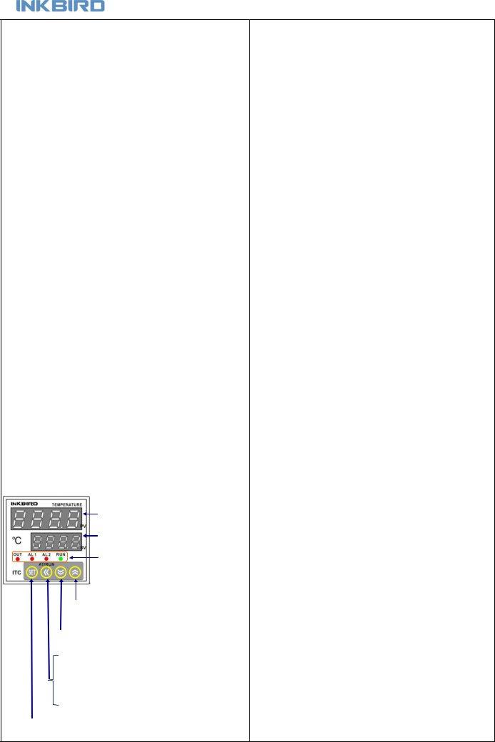
5. Panel instruction
|
|
|
PV window displays |
|
|
|
measured value or set functional symbols |
|
|
||
|
|
|
SV window displays |
|
|
|
|
|
|
|
setting value or set value to be read |
|
|
|
|
|
|
|
Working indicating light |
|
|
|
|
|
|
|
OUT: Indicating control signal output |
|
|
|
|
|
|
|
AL1: Indicating AL1 alarm |
|
|
|
AL2: Indicating AL2 alarm |
Figure 5 |
|
|
RUN: Manual indication |
“INCREASE” key: when setting value, press“ ” key to increase |
|||
value, |
keeping this key to be pressed can increase value quickly. |
||
“DECREASE”key: when setting value, press “ ” key to decrease
value, keeping this key to be pressed can decrease value quickly. “MOVE“ key: when setting temperature value or parameters,
use this key to move cursor to required numerical position.
press this key for over 2 seconds to start or stop
“SET” key: when in normal display mode, press this key to view setting value for control signal output; long press for over 2 seconds to enter parameters setting mode.
6.Operation instruction
6.1Display status
After power on, the instrument will conduct
and monitoring status automatically. PV window displays current measured
value, while SV window displays setting value; If “orAL” was displayed
alternately between PV and SV windows, it means input value exceeded measuring range (or sensors in open loop), or input setting is incorrect. When there was alarm output, SV window will alternately display characters related to the alarms:
HiAL(alarm for high limit),LoAL(Alarm for low limit), dHAL(alarm for plus deviation),dLAL(alarm for minus deviation).
6.2 View output value
Press “SET” key (no longer than 1 second), if SV window displays character “A”(for instance), it indicates automatic control mode, while if the displayed character is “M” (for instance: ), it indicates the manual control mode.
6.3 Automatic/Manual control switch
Press “«” key (no longer than 1 second), the temperature controller can
switch between automatic and manual control mode without interference to the operation. Under automatic control mode, RUN indicating light will off; and under manual control mode, RUN indicating light will on.
(remarks: if the running status of the function setting is “2: forbid manual mode”, above operation is invalid).
6.4 Value setting
When SV window displays setting value, press “ ” key (“ ” key) to increase (decrease) setting value. Press “«” key to move cursor to required numerical position. Keeping “ ” key or “ ” key to be pressed could increase or
decrease the value quickly.
6.5 Launch
When use the instrument for the first time, it’s a must to use the
function of the instrument to determine control parameters (M50, P and t)
for an ideal control effect. Press “«” key for over 2 seconds, then the SV window will display characters “A” and “T” alternately, and the system will
enter
During
Attentions: for temperature controller which had run
it’s a must to set parameter CtrL as “2” before launching another
for detailed operation). The control parameter value will vary according to
setting temperature, therefore, it’s a must to run
frequently used setting value of the system. If the setting value often
changes, run
|
© 2015 Inkbird Inc. All rights reserved. |
3 |
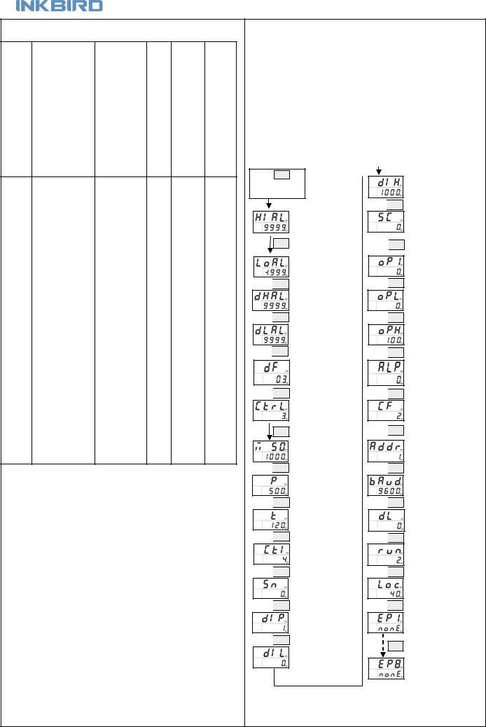
6.7 Parameters setting
Table 2: parameters setting and definition
Parameter |
Definition |
Value range |
Unit |
Default |
Remarks |
|
|
|
|
|
|
HIAL |
Upper alarm limit |
1℃ |
9999 |
See 6.8.1 |
|
|
|
|
|
|
|
LoAL |
Lower alarm limit |
1℃ |
See 6.8.1 |
||
|
|
|
|
|
|
dHAL |
Deviation high alarm |
0~9999 |
1℃ |
9999 |
See 6.8.1 |
|
|
|
|
|
|
dLAL |
Deviation low alarm |
0~9999 |
1℃ |
9999 |
See 6.8.1 |
|
|
|
|
|
|
dF |
Hysteresis band |
0~200.0 |
0.1℃ |
0.3 |
See 6.8.3 |
|
|
|
|
|
|
|
|
0: On/OFF |
|
|
|
CtrL |
Control mode |
1,3: PID |
|
3 |
See 6.10.2 |
|
|
2: |
|
|
|
|
|
|
|
|
|
M50 |
Integral Time |
0~9999 |
0.1℃ |
1000 |
See 6.11.3 |
|
|
|
|
|
|
P |
Differential |
0~9999 |
0.01S/℃ |
500 |
See 6.11.2 |
6.6 Workflow for setting
After instrument powered on and run
key(or “ ” key) to set the value. After value set, press “SET” key to
confirm and go for setting for another function. Then repeat above operation, till all the functions are configured OK.Quit setting mode, and enter PV/SV monitoring mode.
Attentions: if parameters were changed during parameters setting mode, the temperature controller will save the change if there is no further operation for over 10 seconds, and return to PV/SV monitoring mode.
t |
Hysteresis time |
1~9999 |
|
second |
120 |
See 6.11.3 |
|
|
|
|
|
|
|
Ctl |
Control period |
1~120 |
|
second |
4 |
See 6.11.4 |
|
|
|
|
|
|
|
Sn |
Input sensor |
0~42 |
|
|
0 |
See 6.9.1 |
|
|
|
|
|
|
|
diP |
decimal point position |
0~3 |
|
|
1 |
See 6.9.2 |
|
|
|
|
|
|
|
diL |
Displayed value for low |
|
1 Digital |
0 |
See 6.9.3 |
|
limit |
|
|||||
|
|
|
|
|
|
|
diH |
Displayed value for high |
|
1 Digital |
1000 |
See 6.9.3 |
|
limit |
|
|||||
|
|
|
|
|
|
|
|
|
|
|
|
|
|
SC |
Sensor Calibration |
|
|
0 |
See 6.9.5 |
|
|
|
|
|
|
|
|
|
|
0/2:time proportion |
|
|
|
|
oP1 |
Output mode |
|
0 |
See 6.10.1 |
||
|
|
|
|
|
||
|
|
|
|
|
|
|
Opl |
Low limit of output |
0~220 |
|
1% |
0 |
See 6.10.1 |
|
|
|
|
|
|
|
Oph |
High limit of output |
0~220 |
|
1% |
100 |
See 6.10.1 |
|
|
|
|
|
|
|
ALP |
Alarm definition |
0~31 |
|
|
0 |
See 6.8.2 |
|
|
|
|
|
|
|
|
System functions |
2:Heater |
|
|
|
|
CF |
|
|
|
2 |
See 6.8.4 |
|
selection |
3:Cooler |
|
||||
|
|
|
|
|||
|
|
|
|
|
||
|
|
|
|
|
|
|
Addr |
Communication address |
0~63 |
|
|
1 |
See 6.12.1 |
|
|
|
|
|
|
|
Baud |
Communication baud |
0~4800 |
|
|
9600 |
See 6.12.2 |
rate |
|
|
||||
|
|
|
|
|
|
|
|
|
|
|
|
|
|
dl |
Digital filtering |
0~20 |
|
|
0 |
See 6.9.4 |
|
|
|
|
|
|
|
|
|
0: manual |
|
|
|
|
run |
Automatic/Manual |
1: automatic |
|
2 |
|
|
status |
|
|
||||
|
|
|
|
|
|
|
|
|
2: No manual |
|
|
|
|
|
|
|
|
|
|
|
LOC |
Permission of revising |
0~999 |
|
|
40 |
See 6.14 |
parameter |
|
|
||||
|
|
|
|
|
|
|
|
|
|
|
|
|
|
EP1 ~EP8 |
8 definitions for field |
Select Any |
|
|
none |
See 6.13 |
parameter |
Parameters from it |
|
||||
|
|
|
|
|||
Press SET 3S to enter Setting Mode
HIAL:Alarm value for high limit
SET
LOAL:Alarm value for low limit
SET
dHAL:Deviation high alarm
SET
dLAL:Deviation high alarm
SET
dF:Return difference
SET
CtrL:Control mode
SET
M50:Integral Time
SET
P:Rate
SET
t:Hysteresis time
SET
Ctl:Control period
SET
Sn:Input sensor
SET
diP:decimal place
SET
diL:Displayed value for low limit
SET
SET
SET
SET
SET
SET
SET
SET
SET
SET
SET
SET
SET
diH:Displayed value for low limit
SC:Revise displayed value
oP1: Output mode
Opl:Low limit of output
Oph:High limit of output
ALP:Alarm definition
CF:System functions selection
Addr:Communication address
Baud:Communication baud rate
dl:Digital filtering
run:Running status
LOC:Permission of revising parameter
Figure 6:Workflow for setting
|
© 2015 Inkbird Inc. All rights reserved. |
4 |

6.8Parameters related to alarm output: “HiAL, LoAL, dHAL, dLAL、 dF, ALP, CF”
6.8.1Alarm parameters: "HiAL、LoAL、dHAL、dLAL". These parameters are for setting the alarm function of the instrument. When there is alarm condition, the system will output alarm signals to drive alarm relay to act (normally opened contact close/normally closed contact open), and alternately display the alarm reasons in the bottom screen. The alarm will be dismissed once the fault is fixed. Alarm conditions are as following:
HiAL: alarm when measured value is larger than HiAL (PV>HiAL).
LoAL: alarm when measured value is smaller than LoAL (PV<LoAL).
dHAL: alarm when plus deviation is larger than dHAL (PV>SV+dHAL).
dLAL: alarm when minus deviation is smaller than dLAL
Generally, user don’t need 4 alarms in effect at the same time. For any
alarm not required, set it to the maximum value to avoid triggering it. For example, set HiAL=9999,
6.8.2 Defining parameter for alarm"ALP"
Table 3: defining alarm function
Alarm output |
Alarm type |
ALP |
|
|
|
|
|
|
Upper alarm limit |
0 |
|
|
|
|
|
AL1 |
Lower alarm limit |
0 |
|
|
|
||
Deviation high alarm |
0 |
||
|
|||
|
|
|
|
|
Deviation low alarm |
0 |
|
|
|
|
|
|
Upper alarm limit |
1 |
|
|
|
|
|
AL2 |
Lower alarm limit |
2 |
|
|
|
||
Deviation high alarm |
4 |
||
|
|||
|
|
|
|
|
Deviation low alarm |
8 |
|
|
|
|
Above are part of common ALP setting. The setting range is 0 - 31. It defines the output position of 4 alarms
dHAL. It’s defined by following formula:
ALP=A×1+B×2+C×4+D×8+E×16
When A=0, HiAL alarm is output by AL1;
When A=2, HiAL alarm is output by AL2;
When B=0, LoAL alarm is output by AL1;
When B=2, LoAL alarm is output by AL2;
When C=0, dHAL alarm is output by AL1;
When C=1, dHAL alarm is output by AL2;
When D=0, dHAL alarm is output by AL1;
When D=1, dHAL alarm is output by AL2;
When E=0, SV screen will display alternately the alarm symbols, enabling user to know the reasons for alarm quickly;
When E=1, SV screen won’t display alternately the alarm symbols
(except orAL)
Alarm for input exceed measurable range (orAL) could occur when there are improper sensor specification setting, input disconnected or short circuit. If such alarm occurred, the instrument will stop control, and keep the output value as stipulated by parameter oPL. No setting is needed for orAL.
6.8.3 Hysteresis Band (Dead Band) parameter "dF"
For avoiding alarm signals caused by input value fluctuation, and consequently malfunction, the instrument has return difference parameter dF (also called as
6.8.4 Function parameter "CF"
Parameter CF is for selecting some system functions: when CF=2,
it’s heating control; when CF=3, it’s refrigeration control.
6.9Parameters related to input “ Sn, diP, diL, diH, DL, Sc” 6.9.1 Sensor type input “Sn”
Table 4: sensor input code and measuring range
Sensor type |
Input |
Code |
Measuring range |
|
|
|
|
|
|
|
K |
0 |
||
|
|
|
|
|
|
S |
1 |
||
|
|
|
|
|
|
WRe |
2 |
||
|
|
|
|
|
thermocouple |
E |
3 |
||
|
|
|
||
J |
4 |
0~1000ºC |
||
|
||||
|
|
|
|
|
|
T |
5 |
0~1000ºC |
|
|
|
|
|
|
|
B |
6 |
0~1800ºC |
|
|
|
|
|
|
|
N |
7 |
0~1300ºC |
|
|
|
|
|
|
Copper resistor |
Pt100 |
20 |
||
|
|
|
|
|
Platinum resistor |
Cu50 |
21 |
||
|
|
|
|
6.9.2 Decimal point position “diP”
Decimal position “diP” is for selecting displaying accuracy. This setting is only
for display. The internal measuring accuracy is fixed to be 0.1℃. When diP=0, it means the temperature display accuracy is 1℃.
When diP=1, 2 or 3, it means the temperature display accuracy is 0.1℃. When the temperature display accuracy is set to be 0.1℃, while the measured temperature is lower than 1,000℃, the temperature will be displayed with accuracy 0.1℃; when the measured temperature is higher than 1,000℃, the temperature will be displayed with accuracy 1℃.
Changing diP parameter can only influence the display, there is no influence to the measuring accuracy.
6.9.3 Definition parameters "diH" and "diL" for linear input range
Linear input includes signals such as current:
voltage:
range for the signals is
6.9.4 Filtering parameter “dL”
is within
to improve responding speed.
6.9.5 Amendment parameter “Sc”
Parameter “Sc” is for offset amendment for input to compensate the
deviation of sensor or input signal. For thermocouples, if there is deviation
at the cold compensation, use parameter “Sc” to amend.
For example, assume input signal is constant (500℃), and Sc value is
0.0℃, then the measured temperature is 500.0℃; while Sc value is 10.0℃, the measured temperature is 510.0℃. The default value of Sc is 0.
This parameter shouldn’t be amended unless there is need to calibrate
the measurement.
6.10 Parameters related to control output “oPI、oPL、oPH、CtrL”
6.10.1Output mode parameters "oPI", "oPL" and "oPH" are used for limiting output
oPI is the mode of main output signal; oPL and oPH are the output low limit and high limit respectively.
When oPI=0, main output mode is time proportioning output (professional
PID adjustment) or digital adjustment. Models with SSR, relay, and
When oPI=1, output mode is continuous output (for models with linear
|
© 2015 Inkbird Inc. All rights reserved. |
5 |