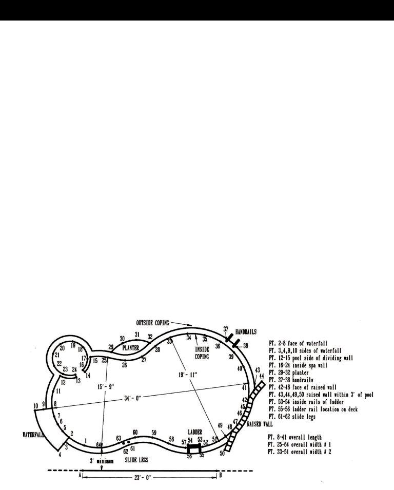
In the foundational toolset of pool safety and maintenance, the Safety Covers Measuring Form emerges as a critical document designed to ensure the precise fitting and installation of pool covers, bolstering safety and durability. This comprehensive form encapsulates essential distributor and dealer information, alongside detailed specifications for the cover itself, ranging from the choice between standard mesh to more specialized options like PROMESH® and HYPERLITE™. The necessity of proper drainage types and aesthetic preferences in color and anchoring systems are highlighted to cater to diverse pool environments and personal tastes. Furthermore, the form delves into meticulous measuring instructions—underscored by the inclusion of the AB line in the pool sketch—aimed at capturing the unique dimensions and characteristics of the pool area. These instructions guide the user through a methodical process from sketching inside dimensions and noting obstructions, to the critical measuring of distances between designated points, ensuring every non-removable detail is accounted for. Special attention is given to potential obstructions and the need for special or extra hardware, underscoring the commitment to a tailored and secure installation. This detailed process, facilitated by the form, exemplifies the thorough approach required to not only secure pools safely but also to enhance the aesthetic integration of safety covers within various pool settings.
| Question | Answer |
|---|---|
| Form Name | Safety Covers Measuring Form |
| Form Length | 3 pages |
| Fillable? | No |
| Fillable fields | 0 |
| Avg. time to fill out | 45 sec |
| Other names | ab measurements pool, safety cover measurement form, gli cover form, pool safety cover measuring |

SAFETY COVER MEASURING FORM
DISTRIBUTOR INFORMATION |
DEALER INFORMATION |
COMPANY NAME: _________________________________ |
COMPANY NAME: _________________________________ |
CITY: __________________ STATE: ___ ZIP: ___________ |
ADDRESS: _____________________________________ |
CONTACT: _____________________________________ |
CITY: ___________________ STATE: ___ ZIP: __________ |
PHONE: __________________ FAX: _________________ |
CONTACT: _____________________________________ |
JOB TAG NAME: __________________________________ |
PHONE: __________________ FAX: _________________ |
COVER SPECIFICATIONS: |
q STANDARD MESH |
q PROMESH® |
q HYPERLITE™ |
q OTHER______________________ |
|
DRAIN TYPE: |
q |
q |
q PUMP IN LIEU OF DRAIN |
|
|
COLOR: |
q BLUE |
q GREEN |
q TAN (HYPERLITE, PROMESH, STANDARD MESH) |
q GRAY (PROMESH & STANDARD MESH) |
|
ANCHORING SYSTEM: |
q CONCRETE |
q WOOD DECK |
q 18” LAWN TUBES |
q 9” PAVER TUBES |
DECK MATERIAL:_______________ |
POOL DRAWING
IMPORTANT! INCLUDE AB LINE IN YOUR SKETCH BELOW.
DISTANCE OF POINT A TO POINT B:_________
215 Sinter Court oungstown, Ohio 44510

MEASURING INSTRUCTIONS
STEP 1
Sketch the inside dimensions of the pool (see example) on the next page. Include all
STEP 2
Using chalk, establish two points A and B (see example). Be sure that A is on the LEFT and B is on the RIGHT while facing the pool. The distance between them should be roughly 2/3 the length of the pool. (i.e. if the pool is 30 ft., make
STEP 3
Make a chalk mark (number each mark) at roughly three (3) foot intervals around the entire pool. Be certain to number all corners, rail locations (front and back of rails), fill spouts, or other obstructions if they are not removable. Mark all points along spa side and pool side of diving wall. Mark areas at one (1) foot intervals when tight radius, rocks, raised walls, waterfalls, or similar obstructions are encountered. Diagrams with these types of obstructions should be accompanied by a photograph. Include width of spa wall or distance between spa and pool, if separate.
STEP 4
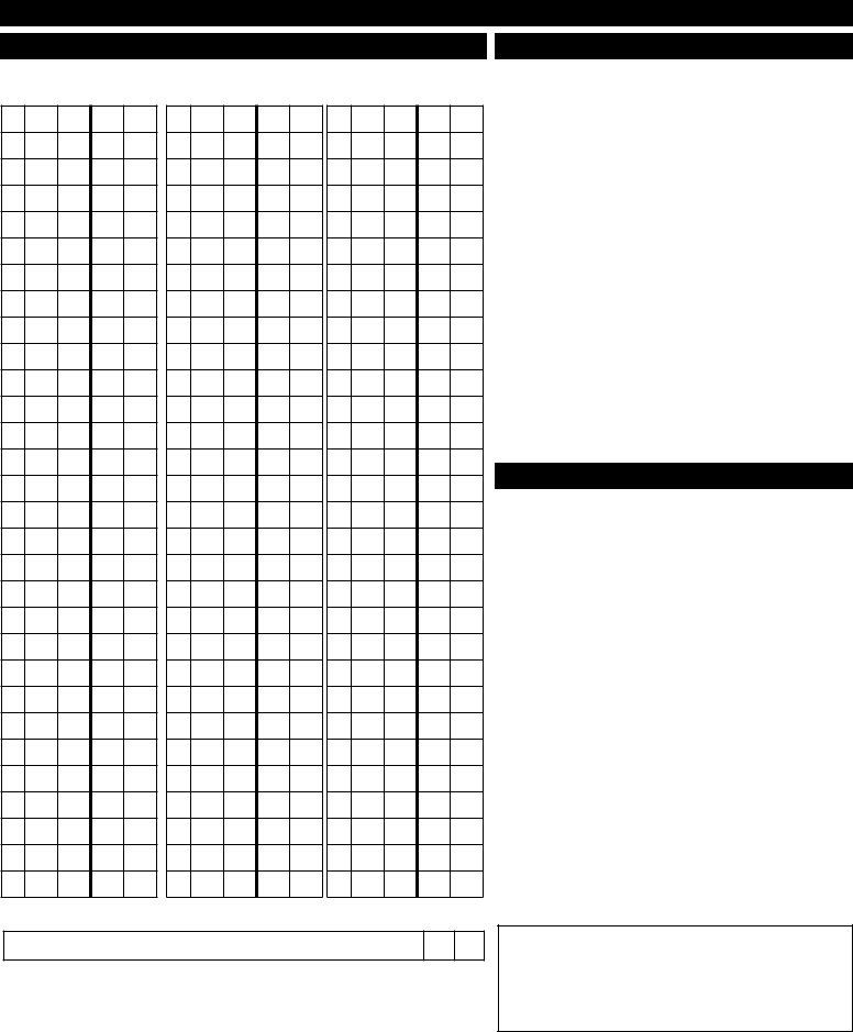
Attach a tape measure to point A. (Pull tape tightly on each measurement). Now measure distance from point A to point 1, then point A to point 2, and so on. List measurements in corresponding columns on the next page (see example). Move tape to point B, and measure in the same fashion; point B to point 1, and so on. Tape should be level and not angel up or down any elevation.
STEP 5
Pick two (2) numbered points representing the overall length of the pool at the water line (see example). List this measurement. Do the same for the overall width of the pool. These measurements are crucial as they act as check points to ensure all other measurements are correct.
215 Sinter Court oungstown, Ohio 44510

|
MEASURING FORMS |
AB POINTS |
OBSTRUCTIONS |
AB
FT IN FT IN
1
2
3
4
5
6
7
8
9
10
11
12
13
14
15
16
17
18
19
20
21
22
23
24
25
26
27
28
29
30
AB
FT IN FT IN
31
32
33
34
35
36
37
38
39
40
41
42
43
44
45
46
47
48
49
50
51
52
53
54
55
56
57
58
59
60
AB
FT IN FT IN
61
62
63
64
65
66
67
68
69
70
71
72
73
74
75
76
77
78
79
80
81
82
83
84
85
86
87
88
89
90
FT IN
OBSTRUCTIONS |
From |
To |
And Pt |
To |
SPECIAL |
||
Pt |
Pt |
Pt |
INFORMATION |
||||
|
|
||||||
q Rock Boulders |
|
|
|
|
q Up & Over |
q Cable |
|
|
|
|
|
|
Length:_______ |
|
|
q Rock Boulders |
|
|
|
|
q Up & Over |
q Cable |
|
|
|
|
|
|
Length:_______ |
|
|
q Gravel/Stone |
|
|
|
|
q Lawn Tubes |
q Paver |
|
|
|
|
|
|
|
|
|
q Waterfall |
|
|
|
|
q Up & Over |
q Cable |
|
|
|
|
|
|
Length:_______ |
|
|
q Grass Area |
|
|
|
|
q Lawn Tubes |
q Paver |
|
|
|
|
|
|
|
|
|
q Planter |
|
|
|
|
q Lawn Tubes |
q Paver |
|
|
|
|
|
|
|
|
|
q Wood Deck |
|
|
|
|
q Wood Deck Anchors |
||
|
|
|
|
|
|
|
|
q Other |
|
|
|
|
q Up & Over |
q Tubes |
|
__________ |
|
|
|
|
Length:_______ |
|
|
|
|
|
|
|
|
||
|
|
|
|
|
|
|
|
|
From |
To |
Height |
|
|
|
|
|
Pt |
Pt |
|
|
|
||
|
|
|
|
|
|||
q Raised Wall |
|
|
|
|
q Up & Over |
q Cable |
|
|
|
|
|
|
Length:_______ |
|
|
q Raised Spa |
|
|
|
|
q One Piece |
q Separate |
|
|
|
|
|
|
|
|
|
SPECIAL OR EXTRA HARDWARE NEEDED
q 2” Brass Anchors |
Entire Pool |
Qt:________ |
|
|
|
|
|
q Brass Flanges |
Entire Pool |
Qt:________ |
|
|
|
|
|
q Paver Tubes |
Entire Pool |
Qt:________ |
|
|
|
|
|
q Lawn Tubes |
Entire Pool |
Qt:________ |
|
|
|
|
|
q Wood Deck Anchors |
Entire Pool |
Qt:________ |
|
|
|
|
|
q |
Entire Pool |
Qt:________ |
|
|
|
|
|
q Standard Installation Rod |
One included |
Qt:________ |
|
|
|
|
|
q “Pro 36” Installation Rod |
1 |
Qt:________ |
|
|
|
|
|
q Standard Springs |
Entire Pool |
Qt:________ |
|
|
|
|
|
q 5” Springs |
Entire Pool |
Qt:________ |
|
|
|
|
|
q Commerical Springs ($) |
Entire Pool |
Qt:________ |
|
*Standard on ProMesh & HyPerLite Custom Covers |
|
|
|
q Other_______________ |
Entire Pool |
Qt:________ |
|
|
|
|
|
|
|
From PT To PT |
|
|
|
|
|
q Longer Tails (Standard Length 20”) |
Entire Pool |
|
|
Required Length = ________ |
|
|
|
|
|
|
|
q Perimeter Padding |
Entire Pool |
|
|
Required Length = ________ |
|
|
|
|
|
|
|
DISTANCE FROM “A” TO “B”
|
FT |
IN |
|
|
|
|
|
|
|
|
|
|
|
Overall Length |
|
|
From PT # |
|
TO PT # |
|
Overall Width |
|
|
From PT # |
|
TO PT # |
|
Optional 2nd Overall Length |
|
|
From PT # |
|
TO PT # |
|
Optional 2nd Overall Width |
|
|
From PT # |
|
TO PT # |
|
Comments / Special Notes:
For directions on “How to Measure a Safety Cover” and to see our quick
215 Sinter Court oungstown, Ohio 44510