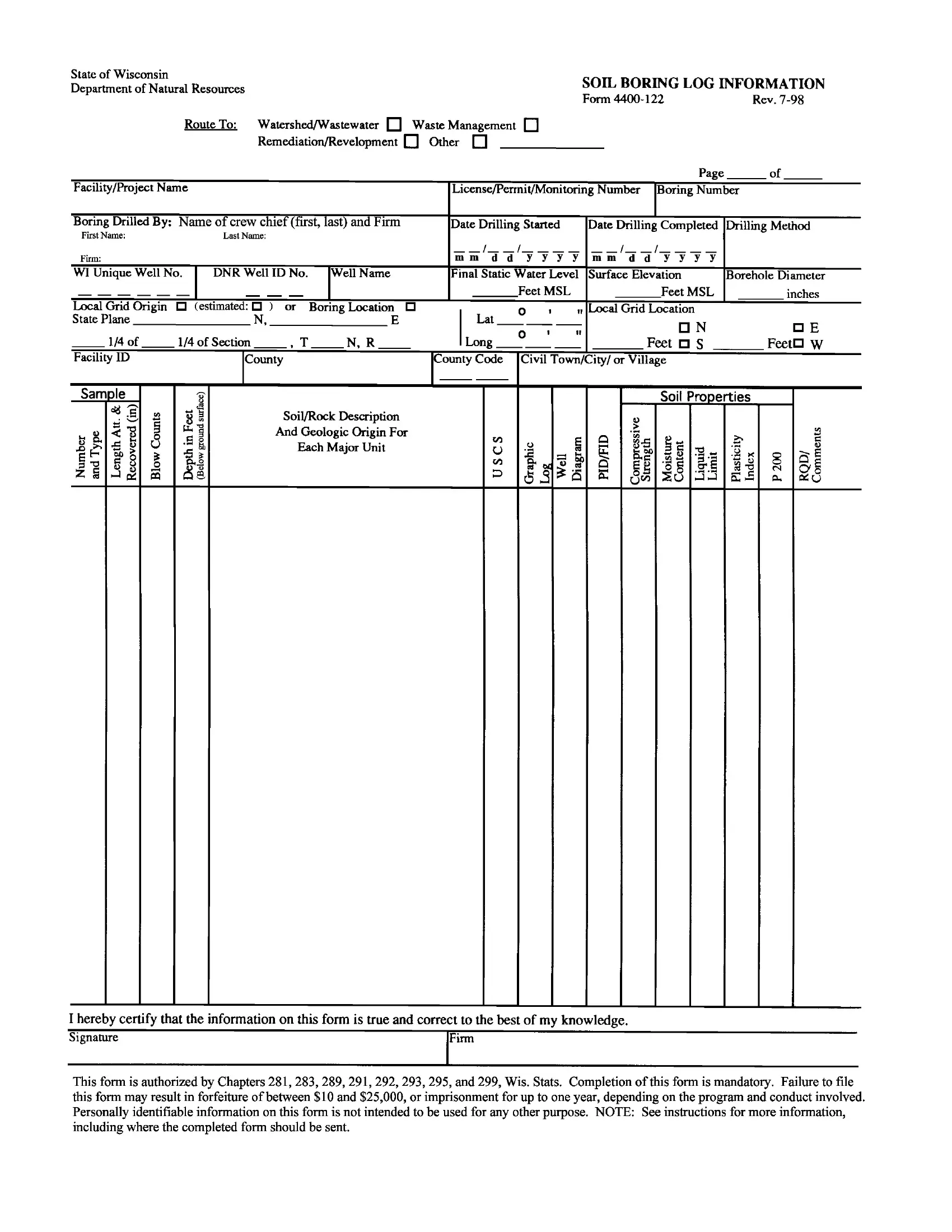
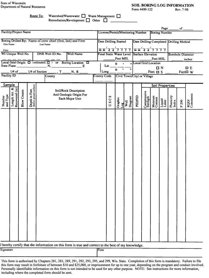
When exploring the essentials of soil analysis in construction and environmental studies, the Soil Boring Log Information Form emerges as a critical document, especially within the guidelines set by the State of Wisconsin Department of Natural Resources. This form, identified as Form 4400-122 and its attachment, Form 4400-122A, plays a pivotal role in recording detailed observations and findings from every boring drilled into the soil. These logs are meticulously filled out to include a wealth of specifics such as the boring's location, the methods used for drilling, and the characteristics of the soil or rock encountered. Additionally, the form provides spaces for noting the start and completion dates of drilling, the drilling crew's details, and any wells established in the boring, complete with their unique identification numbers. A fascinating aspect of this form is the thoroughness with which it approaches the documentation process - from the precise measurement of static water levels to the borehole's diameter and the graphic representation of soil or rock layers. Moreover, the protocol for routing these forms ensures they reach the appropriate departmental program managers, thereby facilitating efficient review and record-keeping. Understanding how to accurately complete and interpret these forms is vital for anyone involved in land development, environmental assessment, or any project requiring subsurface exploration.
| Question | Answer |
|---|---|
| Form Name | Soil Boring Log Template Form |
| Form Length | 4 pages |
| Fillable? | No |
| Fillable fields | 0 |
| Avg. time to fill out | 1 min |
| Other names | bore log sheet, borehole log template excel, borehole log templates, soil boring log template |
State of Wisconsin
Department of Natural Resources
Instructions
Soil Boring Log Information Forms
Form
General Instructions:
Fill out a Soil Boring Log Information Form for every boring drilled. Be sure to indicate the page number and boring number in the blanks at the top of each page. All applicable portions of the Soil Boring Log Information Form must be properly completed. The form must be signed. Form
Routing:
Return this form to the project manager or plan reviewer for the Department program that required the boring. If the project manager/plan reviewer is in a Regional Office, send the original to the Regional Office and a copy to the Central Office in Madison. If the project manager/plan reviewer is in the Central Office, send the original form there and a copy to the Regional Office. If your project does not have a project manager or plan reviewer or you do not know who it is, send the form to the appropriate program in the Central Office. Check the appropriate box at the top of the form to assure proper routing once the form reaches the Department.
Facility/Project Name: List the name of the landfill, wastewater treatment facility, surface impoundment, spill or project.
License/Permit/Monitoring Number: The number assigned by the Department to the facility where the boring was drilled. If unknown, leave blank.
Boring Number: The site boring number or name (e.g.,
Boring Drilled By: The name (first and last) of the drilling crew chief and the drilling firm name.
Date Drilling Started: The date the boring was started in month/day/year (mm/dd/yyyy) format.
Date Drilling Completed: The date the boring was completed in month/day/year (mm/dd/yyyy) format.
Drilling Method: List drilling method used: solid stem auger, hollow stem auger, rotary (air or mud), reverse rotary, cable tool, wash boring, vibratory, etc.
Wisconsin Unique Well Number: If a well is to be set in the boring, fill in the 2 alphabetic 3 numeric Wisconsin Unique Well Number (WUWN) on this form. In addition, attach a WUWN tag to the inside of the protective cover pipe and record that number on the Monitoring Well Construction Form
DNR Well ID Number: The 3 digit number assigned to the well by the Department.
Well Name: If a well is constructed, fill in common well name, such as
Final Static Water Level: The static water level in the borehole in tenths (0.1) of feet above mean sea level prior to abandonment or well construction.
Surface Elevation: The surface elevation of the ground surface at the borehole in tenths (0.1) of feet above mean sea level referenced to the closest USGS benchmark.
Borehole Diameter: The diameter of the borehole in tenths (0.1) of inches.
Local Grid Origin or Boring Location: Check the appropriate box behind the Local Grid Origin or the Boring Location text. Locate the grid origin at a permanent feature near the waste or source of contamination. Give the location in State Plane Coordinates or Latitude and Longitude in degrees, minutes and seconds (using 1927 North American Datum). If State Plane Coordinates are used, circle the appropriate letter for south, central, or north zone. Alternately, an acceptable method for providing this information
without surveying is to locate the Grid Origin on a USGS 7.5 minute quadrangle map. The Location of the Grid Origin can then be interpolated (estimated) using standard cartographic techniques. If the Grid Origin location is estimated, check the estimated box.
The boring location can be determined by surveying or by Global Positioning System (GPS) (with processing to be accurate within 1 foot and reported with precision to hundredths of a second). If the exact location or the boring is given in State Plane Coordinates, then leave the Local Grid Location fields blank.
Section Location of Waste/Source: Enter the quarter quarter section, quarter section, section, township, range and range direction.
Local Grid Location: The location of the boring to the nearest foot, in relation to the grid origin established for the site. If the exact location or the boring is given in State Plane Coordinates, then leave these fields blank.
Facility ID: Fill in the Facility ID (FID) assigned to the site.
County: The county in which the boring is located.
County Code: The
Civil Town/City/or Village: The municipality in which the boring is located.
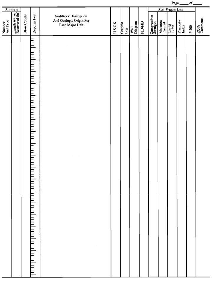
Sample Number: The number used to identify the sample. Indicate the type of sampling apparatus used (i.e. split spoon/ss, Shelby tube/st, grab/gs, piston sampler/ps, core/cs, cuttings/cu). Note the diameter of the sampler in Comments column.
Sample Length Attempted and Recovered: The length of sample attempted and the length of sample recovered reported in inches.
Blow Counts: The number of blow counts per specified length.
Depth: Indicate the depth (below ground surface) of sample collection and depth of any changes in the soil or rock type encountered.
Soil/Rock Description and Geologic Origin: List visual characteristics of soil/rock noted during boring along with any pertinent descriptive remarks. Each major soil unit and bedrock formation shall be described using both subsurface investigations and regional information. Indicate likely geologic origin and Munsell color of the material.
USCS: Indicate the Unified Soil Classification System classification of any unconsolidated units or rock type encountered during boring.
Graphic Log: Graphically illustrate soil/rock types encountered through the depth of boring and provide a key for the symbols used. Indicate the total depth of the boring on the log.
Well Diagram: Graphically show the well casing, well screen length(s), and the location of the top of the filter pack(s) if the boring is converted into a well.
PID/FID: Measurements performed on samples using a
Soil Properties:
Compressive Strength - Standard measurements in tons/ft. Indicate in the Comments column the type of test used.
Moisture Content - Laboratory measurements of percent moisture content. Liquid Limit - Measurement in percent.
Plasticity Index - Measurement in percent.
P 200 - Measurement of percentage of soils smaller than the #200 sieve.
RQD/Comments: Where boring penetrates bedrock, indicate the Rock Quality Designation of the sample. Otherwise, place all comments or remarks in this column and the adjacent margin.