AMENDMENT OF SOLICITATION/MODIFICATION OF CONTRACT
|
2. AMENDMENT/MODIFICATION NO. |
|
3. EFFECTIVE DATE |
4. REQUISITION/PURCHASE REQ. NO. |
|
|
5. PROJECT NO.(If applicable) |
|
0005 |
|
27-Feb-2012 |
|
|
|
PSPS060801PS |
|
|
|
|
|
|
|
|
|
|
|
|
|
6. ISSUED BY |
CODE |
W5J9LE |
7. ADMINISTERED BY (If other than item 6) |
|
CODE |
|
|
|
AFGHANISTAN DISTRICT SOUTH (AES) |
|
|
|
SEE ITEM 6 |
|
|
|
|
|
|
US ARMY CORPS OF ENGINEERS |
|
|
|
|
|
|
|
|
|
|
|
|
|
|
|
|
|
|
|
APO AE 09355 |
|
|
|
|
|
|
|
|
|
|
|
|
|
|
|
|
|
|
|
|
8. NAME AND ADDRESS OF CONTRACTOR (No., Street, County, State and Zip Code) |
X |
9A. AMENDMENT OF SOLICITATION NO. |
|
|
|
|
|
|
|
W5J9LE-12-R-0024 |
|
|
|
|
|
|
|
|
|
|
|
|
|
|
|
|
|
|
X |
9B. DATED (SEE ITEM 11) |
|
|
|
|
|
|
|
|
02-Jan-2012 |
|
|
|
|
|
|
|
|
10A. MOD. OF CONTRACT/ORDER NO. |
|
|
|
|
|
|
|
|
|
|
|
|
|
|
|
|
|
|
|
10B. DATED (SEE ITEM 13) |
|
|
|
|
|
|
|
|
|
|
|
|
|
CODE |
|
|
FACILITY CODE |
|
|
|
|
|
|
|
|
11. THIS ITEM ONLY APPLIES TO AMENDMENTS OF SOLICITATIONS |
|
|
|
|
|
The above numbered solicitation is amended as set forth in Item 14. The hour and date specified for receipt of Offer |
|
is extended, |
X |
is not extended. |
Offer must acknowledge receipt of this amendment prior to the hour and date specified in the solicitation or as amended by one of the following methods:
(a) By completing Items 8 and 15, and returning 1 copies of the amendment; (b) By acknowledging receipt of this amendment on each copy of the offer submitted; or (c) By separate letter or telegram which includes a reference to the solicitation and amendment numbers. FAILURE OF YOUR ACKNOWLEDGMENT TO BE RECEIVED AT THE PLACE DESIGNATED FOR THE RECEIPT OF OFFERS PRIOR TO THE HOUR AND DATE SPECIFIED MAY RESULT IN
REJECTION OF YOUR OFFER. If by virtue of this amendment you desire to change an offer already submitted, such change may be made by telegram or letter, provided each telegram or letter makes reference to the solicitation and this amendment, and is received prior to the opening hour and date specified.
12.ACCOUNTING AND APPROPRIATION DATA (If required)
13.THIS ITEM APPLIES ONLY TO MODIFICATIONS OF CONTRACTS/ORDERS. IT MODIFIES THE CONTRACT/ORDER NO. AS DESCRIBED IN ITEM 14.
A.THIS CHANGE ORDER IS ISSUED PURSUANT TO: (Specify authority) THE CHANGES SET FORTH IN ITEM 14 ARE MADE IN THE CONTRACT ORDER NO. IN ITEM 10A.
B.THE ABOVE NUMBERED CONTRACT/ORDER IS MODIFIED TO REFLECT THE ADMINISTRATIVE CHANGES (such as changes in paying office, appropriation date, etc.) SET FORTH IN ITEM 14, PURSUANT TO THE AUTHORITY OF FAR 43.103(B).
C.THIS SUPPLEMENTAL AGREEMENT IS ENTERED INTO PURSUANT TO AUTHORITY OF:
D.OTHER (Specify type of modification and authority)
is required to sign this document and return |
|
copies to the issuing office. |
|
|
|
14.DESCRIPTION OF AMENDMENT/MODIFICATION (Organized by UCF section headings, including solicitation/contract subject matter where feasible.)
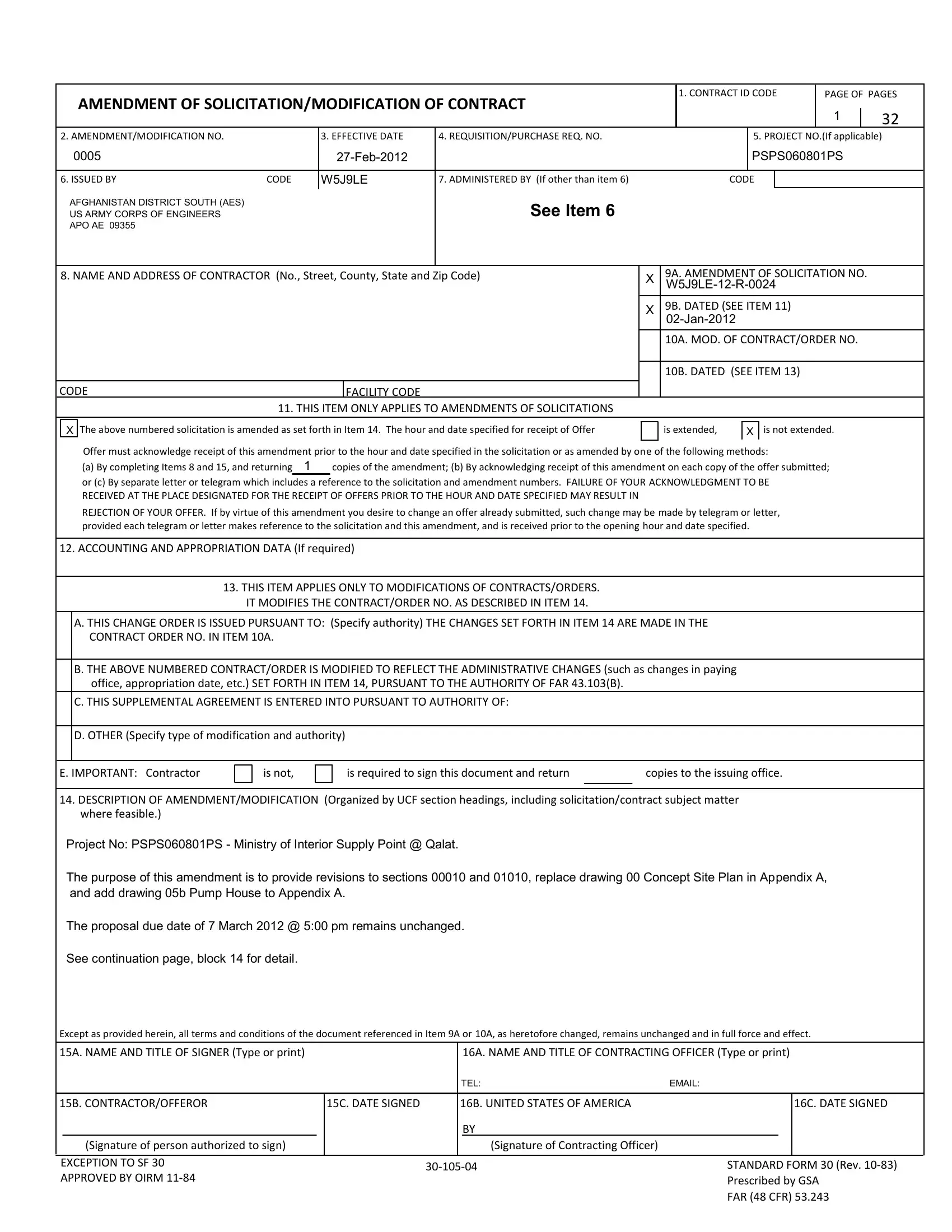
Project No: PSPS060801PS - Ministry of Interior Supply Point @ Qalat.
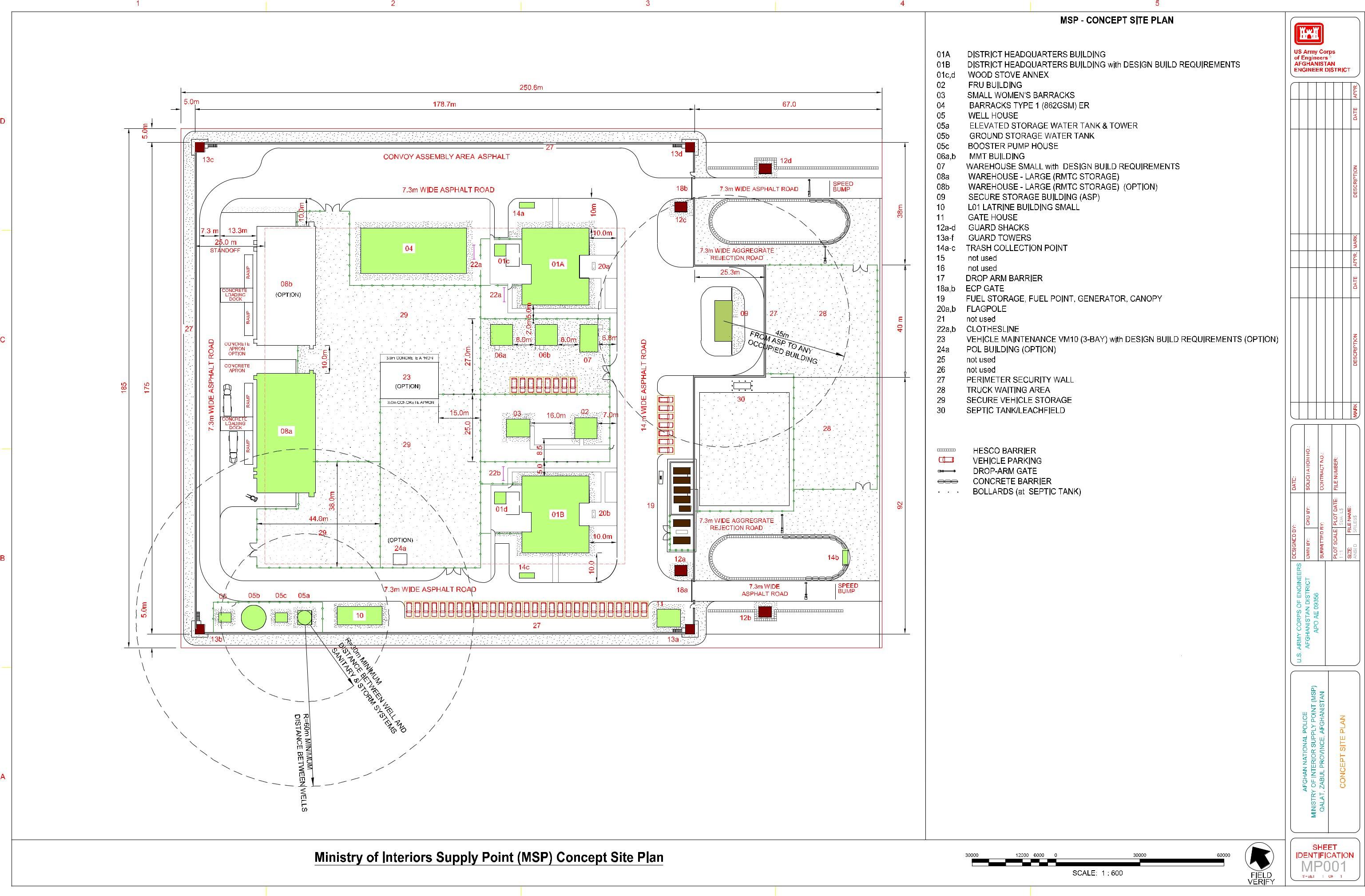
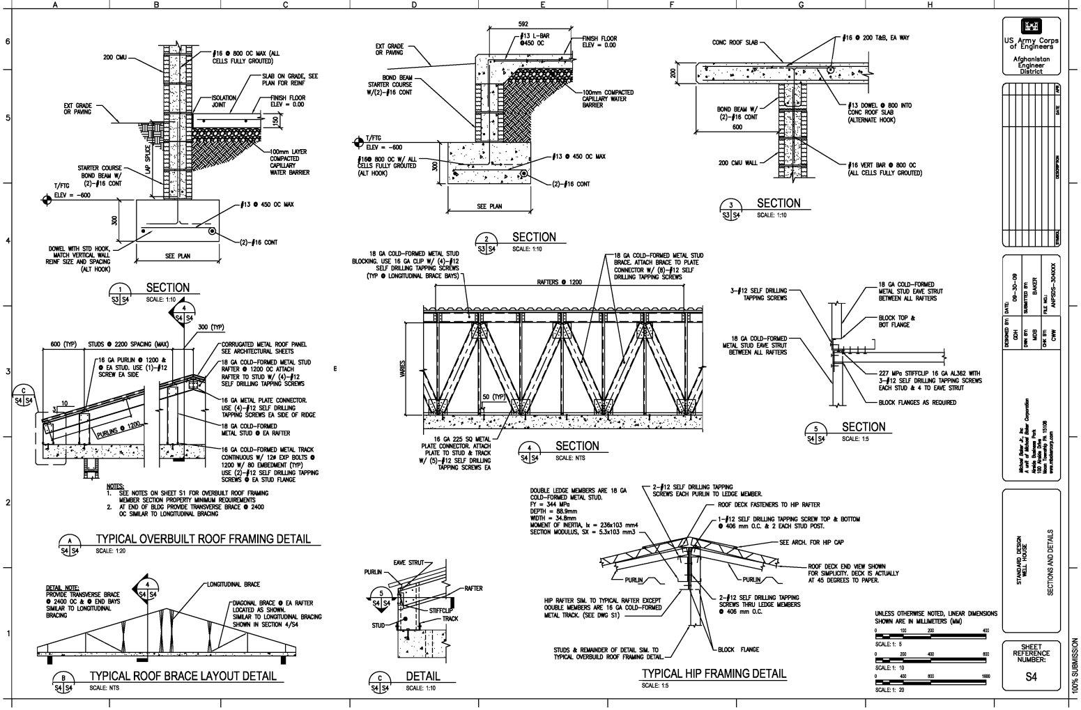
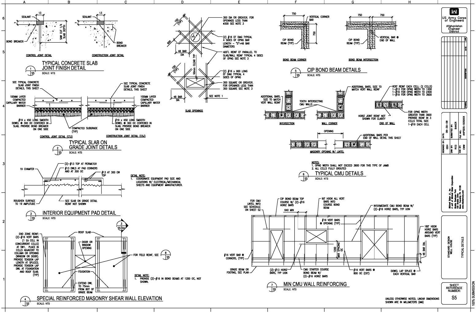
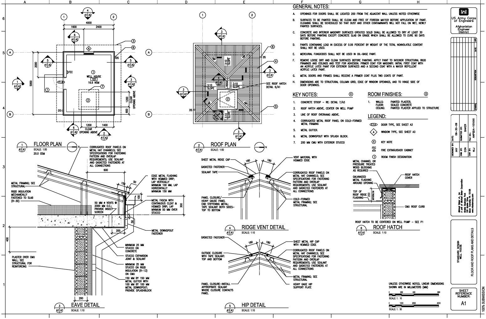
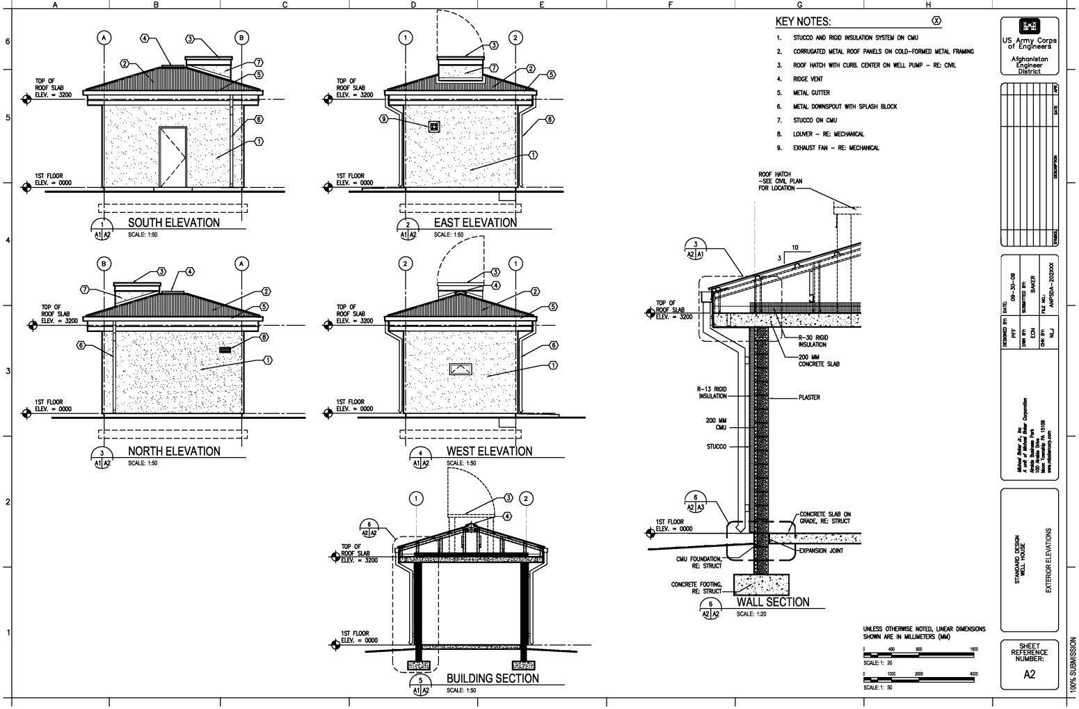
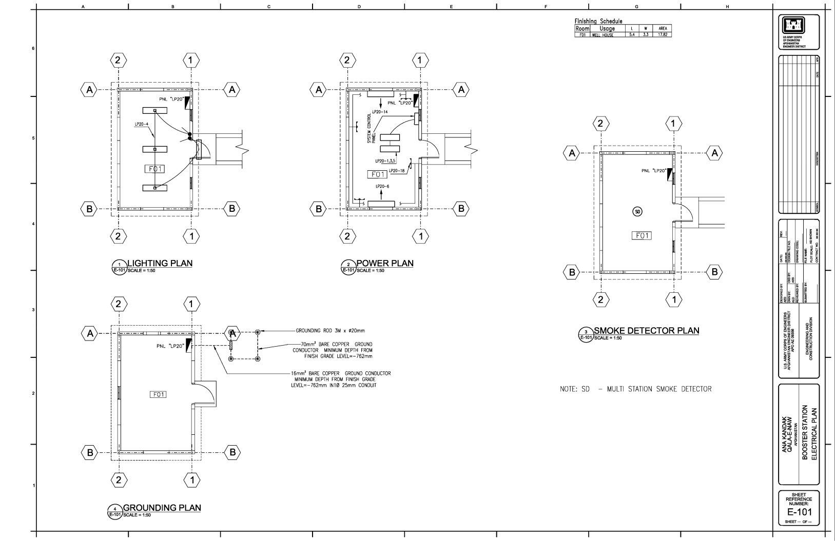
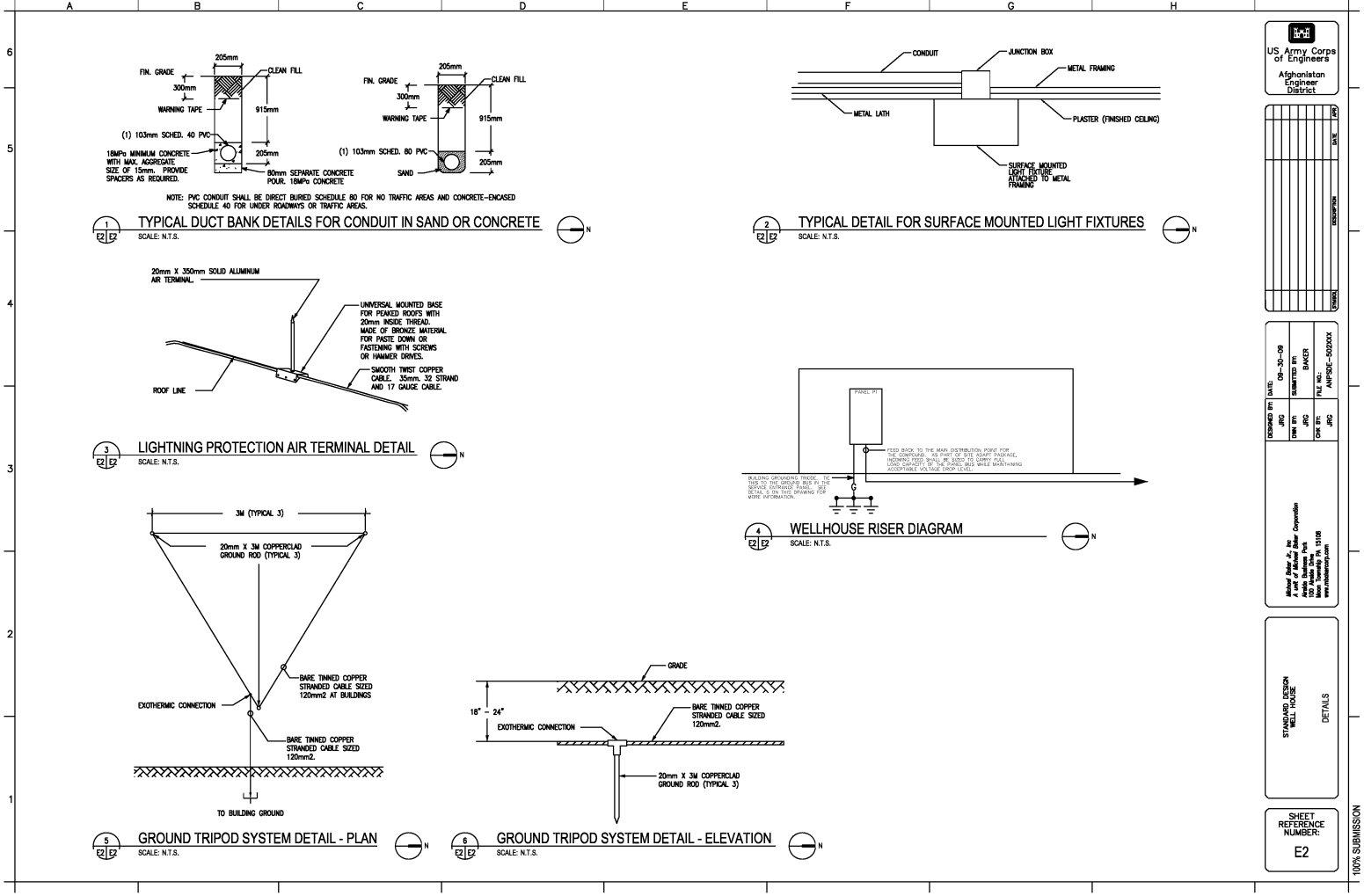
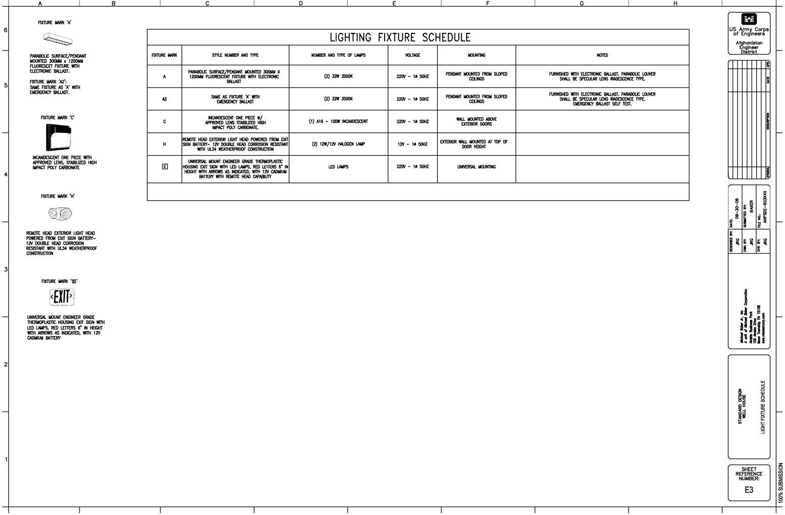
The purpose of this amendment is to provide revisions to sections 00010 and 01010, replace drawing 00 Concept Site Plan in Appendix A, and add drawing 05b Pump House to Appendix A.
The proposal due date of 7 March 2012 @ 5:00 pm remains unchanged.
See continuation page, block 14 for detail.
Except as provided herein, all terms and conditions of the document referenced in Item 9A or 10A, as heretofore changed, remains unchanged and in full force and effect.
15A. NAME AND TITLE OF SIGNER (Type or print) |
|
|
|
|
16A. NAME AND TITLE OF CONTRACTING OFFICER (Type or print) |
|
|
|
|
|
TEL: |
EMAIL: |
|
|
|
|
|
|
|
|
|
|
|
15B. CONTRACTOR/OFFEROR |
|
15C. DATE SIGNED |
|
16B. UNITED STATES OF AMERICA |
|
|
16C. DATE SIGNED |
|
|
|
|
|
|
BY |
|
|
|
|
|
(Signature of person authorized to sign) |
|
|
|
|
(Signature of Contracting Officer) |
|
|
|
|
|
|
|
|
|
|
|
|
|
|
EXCEPTION TO SF 30 |
|
|
30-105-04 |
STANDARD FORM 30 (Rev. 10-83) |
APPROVED BY OIRM 11-84 |
|
|
|
|
|
Prescribed by GSA |
FAR (48 CFR) 53.243
W5J9LE-12-R-0024
Page 2 of 16
SECTION SF 30 BLOCK 14 CONTINUATION PAGE
SUMMARY OF CHANGES
The following have been added by full text:
Section 00010 (Proposal Schedule) provided in this amendment replaces all previous versions issued in their entirety.
Summary of changes:
Corrected CLIN numbering and added CLIN for Pump House
Section 01010 (Scope of Work) provided in this amendment replaces all previous versions issued in their entirety. Summary of Changes:
Corrected paragraph numbering from previous version.
Added paragraph 2.5.9 Pump House.
Appendix A (Standard Design Drawings) is changed as follows:
Drawing 00 Concept Site Plan provided in this amendment replaces all previous versions issued in their entirety. Drawing 05b Pump House provided in this amendment is added.
See pages following for revised/added documents referenced above.
W5J9LE-12-R-0024
Page 3 of 16
SECTION 00010 (AMENDMENT 0005)
PROPOSAL SCHEDULE
The Contractor shall provide a price for all items, including any labeled “Optional Items”.
ITEM |
DESCRIPTION |
QTY |
UNIT |
Unit Price |
AMOUNT |
|
|
|
|
|
|
0001 |
GENERAL |
|
|
|
|
|
|
|
|
|
|
0001AA |
Mobilization/Demobilization |
1 |
LS |
XXX |
$___________ |
|
|
|
|
|
|
0001AB |
Security |
1 |
LS |
XXX |
$___________ |
|
|
|
|
|
|
0001AC |
Unexploded Ordinance (UXO) |
|
|
|
|
|
Removal and Clearance |
1 |
LS |
XXX |
$___________ |
|
|
|
|
|
|
0002 |
DESIGN PROGRAM |
|
|
|
|
|
|
|
|
|
|
|
|
|
|
|
|
0002AA |
Site Survey |
1 |
LS |
XXX |
$___________ |
|
|
|
|
|
|
0002AB |
Geotechnical Report |
1 |
LS |
XXX |
$___________ |
|
|
|
|
|
|
0002AC |
A/E Design |
1 |
LS |
XXX |
$___________ |
|
|
|
|
|
|
0002AD |
Record Drawings |
1 |
LS |
XXX |
$___________ |
|
|
|
|
|
|
0003 |
SITE DEVELOPMENT |
|
|
|
|
|
|
|
|
|
|
|
|
|
|
|
|
0003AA |
Site Demolition |
1 |
LS |
XXX |
$___________ |
|
|
|
|
|
|
0003AB |
Site Grading and Stormwater |
|
|
|
|
|
Management |
1 |
LS |
XXX |
$___________ |
|
|
|
|
|
|
0003AC |
Well |
1 |
LS |
XXX |
$___________ |
|
|
|
|
|
|
0003AD |
Potable Water System and |
|
|
|
|
|
Storage |
1 |
LS |
XXX |
$___________ |
|
|
|
|
|
|
0003AE |
Wastewater Collection and |
|
|
|
|
|
Treatment Plant |
1 |
LS |
XXX |
$___________ |
|
|
|
|
|
|
0003AF |
Electrical Generation and |
|
|
|
|
|
Distribution System |
1 |
LS |
XXX |
$___________ |
|
|
|
|
|
|
0003AG |
Communication System |
1 |
LS |
XXX |
$___________ |
|
|
|
|
|
|
0003AH |
Fuel Storage, Generator |
|
|
|
|
|
Canopy, and Vehicle Fuel |
|
|
|
|
|
Point |
1 |
LS |
XXX |
$___________ |
|
|
|
|
|
|
0003AJ |
Concrete Sidewalks |
1 |
LS |
XXX |
$___________ |
|
|
|
|
|
|

|
|
|
|
|
W5J9LE-12-R-0024 |
|
|
|
|
|
Page 4 of 16 |
|
|
|
|
|
|
|
0003AK |
Concrete Loading Dock, |
|
|
|
|
|
|
Ramp and Apron |
1 |
LS |
XXX |
$___________ |
|
|
|
|
|
|
|
|
0003AL |
Asphalt Roadways/Driveways |
1 |
LS |
XXX |
$___________ |
|
|
|
|
|
|
|
|
0003AM |
Aggregate Roadways, Parking |
|
|
|
|
|
|
and Groundcover |
1 |
LS |
XXX |
$___________ |
|
|
|
|
|
|
|
|
0003AN |
Flagpoles |
4 |
LS |
XXX |
$___________ |
|
|
|
|
|
|
|
|
0004 |
FORCE PROTECTION |
|
|
|
|
|
|
|
|
|
|
|
|
0004AA |
Perimeter Security Wall |
1 |
LS |
XXX |
$___________ |
|
|
|
|
|
|
|
|
0004AB |
Fencing, Gates and Barriers |
1 |
LS |
XXX |
$___________ |
|
|
|
|
|
|
|
|
0005 |
FACILITIES |
|
|
|
|
|
|
|
|
|
|
|
|
0005AA |
Administration Bldg |
2 |
EA |
$_________ |
$___________ |
|
|
|
|
|
|
|
|
0005AB |
Wood Stove annex |
2 |
EA |
$_________ |
$___________ |
|
|
|
|
|
|
|
|
0005AC |
FRU Building |
1 |
EA |
$_________ |
$___________ |
|
|
|
|
|
|
|
|
0005AD |
Small Women’s Barracks |
1 |
EA |
$_________ |
$___________ |
|
|
|
|
|
|
|
|
0005AE |
Senior Barracks |
1 |
EA |
$_________ |
$___________ |
|
|
|
|
|
|
|
|
0005AF |
Well House |
1 |
EA |
$_________ |
$___________ |
|
|
|
|
|
|
|
|
0005AG |
Pump House |
1 |
EA |
$_________ |
$___________ |
|
|
|
|
|
|
|
|
0005AH |
MMT Buildings |
2 |
EA |
$_________ |
$___________ |
|
|
|
|
|
|
|
|
0005AJ |
Warehouse (Small) |
1 |
EA |
$_________ |
$___________ |
|
|
|
|
|
|
|
|
0005AK |
Warehouse, Large (RMTC) |
1 |
EA |
$_________ |
$___________ |
|
|
|
|
|
|
|
|
0005AL |
Secure Storage Building |
|
|
|
|
|
|
(ASP) |
1 |
EA |
$_________ |
$___________ |
|
|
|
|
|
|
|
|
0005AM |
Latrine |
1 |
EA |
$_________ |
$___________ |
|
|
|
|
|
|
|
|
0005AN |
Gate House |
1 |
EA |
$_________ |
$___________ |
|
|
|
|
|
|
|
|
0005AP |
Guard Shacks |
4 |
EA |
$_________ |
$___________ |
|
|
|
|
|
|
|
|
0005AQ |
Guard Towers |
4 |
EA |
$_________ |
$___________ |
|
|
|
|
|
|
|
|
0005AR |
Trash Collection Point |
3 |
EA |
$_________ |
$___________ |
|
|
|
|
|
|
|
|
0005AS |
Clothesline |
2 |
EA |
$_________ |
$___________ |
|
|
|
|
|
|
|
|

W5J9LE-12-R-0024
Page 5 of 16
|
0006 |
DBA Insurance |
|
|
|
|
|
SUBCLINS 0001- 0005 |
1 |
LS |
XXX |
$___________ |
|
|
The amount listed by the offeror on this CLIN is the estimated DBA insurance premium (estimated payroll of the offeror and its subcontractors, multiplied by the applicable rate(s)). The actual amount paid by the government under this CLIN will be based on the amount of the Rutherfoord invoice submitted by the offeror after contract award. In the event of recalculation of the premium by CNA based on actual payroll amounts, the Contracting Officer will adjust this CLIN by contract modification to reflect actual premium amounts paid.
|
TOTAL BASE BID ITEMS: |
|
|
|
$__________ |
|
|
|
|
|
|
|
OPTIONAL BID ITEMS |
|
|
|
|
|
|
|
|
|
|
0007 |
FACILITIES |
|
|
|
|
|
|
|
|
|
|
|
Vehicle Maintenance Facility |
|
|
|
|
0007AA |
and POL Bldg. |
1 |
LS |
$_________ |
$___________ |
|
|
|
|
|
|
|
DBA Insurance, SUBCLIN |
|
|
|
|
0007AB |
0008AA |
1 |
LS |
$_________ |
$___________ |
The amount listed by the offeror on this CLIN is the estimated DBA insurance premium (estimated payroll of the offeror and its subcontractors, multiplied by the applicable rate(s)). The actual amount paid by the government under this CLIN will be based on the amount of the Rutherfoord invoice submitted by the offeror after contract award. In the event of recalculation of the premium by CNA based on actual payroll amounts, the Contracting Officer will adjust this CLIN by contract modification to reflect actual premium amounts paid.
|
|
|
|
|
|
0007AC |
Warehouse (Large) |
1 |
LS |
$_________ |
$___________ |
|
|
|
|
|
|
|
DBA Insurance for SUBCLIN |
|
|
|
|
0007AD |
0008AC |
1 |
LS |
$_________ |
$___________ |
The amount listed by the offeror on this CLIN is the estimated DBA insurance premium (estimated payroll of the offeror and its subcontractors, multiplied by the applicable rate(s)). The actual amount paid by the government under this CLIN will be based on the amount of the Rutherfoord invoice submitted by the offeror after contract award. In the event of recalculation of the premium by CNA based on actual payroll amounts, the Contracting Officer will adjust this CLIN by contract modification to reflect actual premium amounts paid.
TOTAL OPTIONAL BID ITEMS
SCHEDULE TOTAL:
W5J9LE-12-R-0024
Page 6 of 16
PROPOSAL SCHEDULE NOTES:
1.Offeror shall submit prices on all items. Scope of Work for each item are described in Section 01010.
2.Only one contract for the entire schedule will be awarded under this solicitation. This project will be awarded as a single contract.
3.EVALUATION OF OPTIONAL BID ITEMS: The award will be made to the offeror whose proposal represents the lowest, responsive and responsible bidder. For pricing purposes the Government will evaluate both the Base Proposals and Option Proposals. The Government is not obligated to exercise the options.
4.EXERCISE OF OPTIONAL BID ITEMS: Optional Bid Items may, at the option of the Government, be added to the contract at any time within one-hundred eighty (180) calendar days after receipt of the Notice to Proceed.
5.PERIOD OF PERFORMANCE AND LIQUIDATED DAMAGES: See Section 00150 for performance schedule. Period of performance is defined as the number of calendar days from receipt of Notice to Proceed. Liquidated Damages are included in this contract. See FAR Clause 52.211-12.
6.Abbreviations:
LM = Linear meters SM = Square meters m2 = square meters kPa = kilopascals m = meters
cm = centimeters l = liters
kVA = kilo volt amps
- END OF SECTION-
W5J9LE-12-R-0024
Page 7 of 16
SECTION 01010
SCOPE OF WORK
1.0PROJECT REQUIREMENTS
This project consists of the design and construction of site improvements and construction of facilities to support the Afghanistan National Police (ANP) program for one (1) Ministry of Interior Supply Point with Police Precinct (MSP) Compound to be located in Qalat, Zabul Province, Afghanistan.
This project is defined as the management, planning, design, material, labor, and equipment, to site adapt and construct all utilities, vehicular access, buildings, force protection measures, site security, mine clearance activities, and all other features as required herein.
1.1CODES AND STANDARDS
The work within this contract shall meet and be constructed in accordance with this Section 01010 Scope of Work, Government provided drawings located in Appendix A, Section 01015 Technical Requirements, Technical Specifications located in Appendix B, and the most recent Life Safety and building codes including:
Current U.S. design and International Building Code
NFPA-101
UFC 4-010-01, DoD Anti-Terrorism Standards: Force Protection and Security Standards for Buildings
AED Design Guides
1.2LOCATION
The site is located in Zabul Province, Afghanistan, as shown on the attached site assessment. The coordinates of it’s boundaries are:
Corner |
Latitude (N) |
Longitude (E) |
1 |
32 04 26.8N |
66 52 25.6E |
2 |
32 04 21.7N |
66 52 30.5E |
3 |
32 04 27.9N |
66 52 38.4E |
4 |
32 04 34.1N |
66 52 33.0E |
1.3GENERAL REQUIREMENTS
1.3.1DESIGN POPULATION
Compound shall have a design population of 200 personnel for purposes of utility designs.
1.3.2EQUIVALENCE
Any standard that can be determined to be substantially equivalent to the standards specified in this document may be used, but it is the Contractor’s responsibility to show the equivalency of the alternate standard. Reviewable
documentation must be provided to the Contracting Officer (KO) for approval prior to use; no part of any time lost due to such actions shall be made the subject of claim for extension of time, excess costs, or damages by the Contractor.
1.3.3AFGHAN LABOR AND MATERIALS
The Contractor is encouraged to use Afghan labor and subcontractors to the maximum extent possible commensurate with technical, security or other requirements or necessary considerations. The intent of this Contract is also to use locally procured materials and labor to the maximum extent possible, but this does not allow the
W5J9LE-12-R-0024
Page 8 of 16
Contractor to make changes to the Standard Design drawings, Technical Specifications or design analysis, except where specifically indicated herein.
1.3.4SITE ADAPTING OF GOVERNMENT STANDARD DRAWINGS
Government-furnished drawings may require adaptation to conform to actual existing site conditions. All such adaptations shall be designed and constructed in accordance with current U.S. and International Building Codes and all requirements herein. The contractor must submit any changes to the Government-provided Drawings or
Specifications in accordance with Contract Section 01335, Paragraph “Variations.” Adaptations shall be approved by the Contracting Officer’s Representative (COR) prior to the start of work.
Verify all site dimensions and all existing conditions described both herein and in Appendices drawings prior to the start of any construction. The Contractor is highly encouraged to verify existing site conditions before submitting proposals.
Structural foundations in Government provided Standard designs have been designed for a maximum soil bearing capacity of 0.75 kg/cm2. The geotechnical investigation shall confirm bearing capacity to be no less than 0.75 kg/cm2: or if investigation determines capacity to be less than 0.75 kg/cm2, Contractor shall redesign all foundations based on the values provided in the geotechnical investigations.
All standard construction amenities such as underground utilities, site grading, electrical, communications infrastructure, detailing etc. shall be implied as design and construction requirements.
1.3.5ORDER OF PRECENDENCE
For questions of conflict or ambiguity in contract documents or drawings refer to Section 00555 DESIGN CONCEPT DOCUMENTS for Order of Precedence.
1.3.6ENGISH LANGUAGE REQUIREMENT
All information shall be presented in English. The Contractor shall have a minimum of one English-speaking representative present to communicate with the COR at all times when work is in progress.
1.3.7SUBMITTALS
Refer to Section 01335 SUBMITTAL PROCEEDURES for all Submittal and Submittal Register requirements.
1.3.8CQM TRAINING REQUIREMENT
Refer to Section 01451 CONTRACTOR QUALITY CONTROL for Construction Quality Management (CQM) Training requirements.
2.0SUMMARY OF WORK
2.1GENERAL
2.1.1MOBILIZATION / DEMOBILIZATION
Mobilization and Demobilization shall consist of all labor, equipment, supplies and facilities required to stage all equipment and facilities needed for construction of this project. Requirements for mobilization and temporary structures are set forth in Section 01015 Technical Requirements and 01060 Special Requirements.
W5J9LE-12-R-0024
Page 9 of 16
2.1.2SECURITY
Security is critical to construction in Afghanistan, especially on roads and remote areas away from Coalition Force bases. The Contractor must have an appropriate amount of security/protection to match the threat in the project area and along the supply routes. A detailed security plan in accordance with Section 01040 Security shall be approved by the Government before being issued a Clearance For Construction.
The Contractor shall be responsible for physical security of all materials, supplies, and equipment of every description, including property which may be Government-furnished or owned, for all areas occupied jointly by the Contractor and the Government, as well as for all work performed.
The Contractor shall provide perimeter force protection security for the developing site. Security may include, but is not limited to, a perimeter fence and private security guards. Perimeter security shall prevent unauthorized site access and provide safety protection to the Contractor work force and government personnel for the duration of the project. The Contractor is solely responsible for security; however, local police shall be coordinated with regarding security.
2.1.3UNEXPLODED ORDINANCE (UXO) REMOVAL AND CLEARANCE
Contractor IS responsible for initial clearance/removal.
The Contractor shall search for, identify and clear all mines and unexploded ordnance (UXO) from the entire site. The contractor may only provide clearance/removal services via UN Mine Action Center for Afghanistan (UNMACA) accredited entities, and clearance shall be accomplished to the anticipated foundation depth as indicated in the contract. If sub-surface construction activities are to be performed on this site the minimum clearance depth will be 1 meter. Sub-surface clearance for construction activities in excess of 1 meter as defined by the contract parameters will also be the responsibility of the contractor. Clearance by definition is an investigation and clearance of all sub-surface metallic anomalies on the site. Clearance/removal may only be undertaken in accordance with International Mine Action Standards (IMAS), Afghanistan Mine Action Standards (AMAS), and
applicable U.S. Army Corps of Engineer (USACE) Ordnance & Explosives (OE) safety standards. When mines and/or UXO’s are identified, the Contractor shall place them in a location in accordance with IMAS/AMAS/USACE
until destruction of the items can take place. Construction work shall not occur inside the safety exclusion zone based on the most probable munition (MPM) expected on the site. Construction will not commence in any area that has not been cleared to the specified depth.
The contractor will provide a standard UXO/Mine Clearance safety work plan to the US Army Corps of Engineers UXO / Mine Clearance COR for review prior to commencement of all UXO/mine clearance activities on the project sites. Once the UXO/ Mine Clearance has concluded, the contractor shall provide the US Army Corps of Engineers UXO / Mine Clearance COR a clearance certificate for review and approval before any construction activities are to commence.
NOTE 1: The USACE does not need written clearance certificate approval from the UNMACA to approve the construction start activities. However, the contractor is responsible for providing a copy of the clearance certificate to the UNMACA for entry into their country wide database. A final signed copy of the UNMACE certificate must then be provided to the USACE UXO/Mine Clearance COR.
It is the responsibility of the Contractor to be aware of the risk of encountering UXO/mines and to take all actions necessary to assure a safe work area to perform the requirements of this contract. The Contractor assumes the risk of any and all personal injury, property damage or other liability arising out of or resulting from any Contractor action taken hereunder. The Contractor and its subcontractors may not handle, work with, move, transport, render safe, or disarm any UXO/mine, unless they have appropriate accreditations under the IMAS/AMAS from the UNMACA.
If a UXO/mine is encountered after a UNMACA-approved clearance certificate is provided to the Government, UXO/mine disposal shall be handled in accordance with Section 01015, Technical Requirements.
NOTE 2: Point of Contact for UXO/Mine Clearance Safety Work Plan review and approval shall be directed to the US Army Corps of Engineers Mine Clearance Safety/COR:
UXO Safety/ Demining COR, USACE
W5J9LE-12-R-0024
Page 10 of 16
tas.uxo.demining.safety@usace.army.mil, Roshan:079-403-1452 Comm:540-723-6129
2.2DESIGN PROGRAM
2.2.1SITE SURVEY
The Site Survey shall consist of all labor, equipment and supplies necessary to produce the topographical and other data in accordance with the requirements specified in Sections 01015 and 01335.
2.2.2GEOTECHNICAL REPORT
The Geotechnical Report shall contain the results of a geotechnical investigation conducted in accordance with the requirements specified in Section 01015. All labor, equipment and supplies necessary to conduct a geotechnical investigation shall be considered a part of the Geotechnical Report.
2.2.3A/E DESIGN
A/E (Architectural/Engineering) Design shall consist of all labor, equipment and supplies required to furnish a completed project design in accordance with the requirements specified herein, and in Section 01015 and Section 01335.
2.2.3.1 MASTER PLAN
The Contractor shall prepare a programmatic Master (Site) Plan, designed to include all requirements (including planned locations for Optional Bid Items) required herein. The Master Plan shall include all locations of construction office/storage containers, lay-down and construction debris removal area.
Development of the compound should utilize the most suitable land for construction, and shall be planned in accordance with the Concept Site Plan. Facilities shall not be located in wadis or dry river beds. The sidewalk network as illustrated on the Concept Site Plan shall be modified so that sidewalks are located to connect to building entrances.
Contractor is required to plant new trees equal to the quantity of demolished trees.
The proposed costs of the Master Plan shall be included as part of the line item “A/E Design” in the 00010 Bid Schedule.
2.2.4RECORD DRAWINGS
Record Drawings shall consist of all labor, equipment and supplies required to produce Record (As-Built) Drawings in accordance with the requirements specified in Section 01335 and 01780A.
2.3SITE DEVELOPMENT
2.3.1SITE DEMOLITION
The Contractor shall dispose of all existing vegetation and debris and demolish any and all existing structures which may be present on site including all concrete, foundations and utilities prior to commencement of new work.
2.3.2SITE GRADING AND STORMWATER MANAGEMENT
Site grading and drainage features shall conform to the requirements and references as specified in Section 01015 Technical Requirements. All drainage shall be conveyed off site; stormwater retention is not permitted as a drainage solution. Site grading shall not adversely impact the drainage on neighboring properties.
W5J9LE-12-R-0024
Page 11 of 16
2.3.2.1MITIGATION OF ONSITE WADIS (NOTE: ONLY USE IF SITE ASSESSMENT SHOWS MAJOR WADIS)
Contractor shall provide additional backfill and compaction to elevate and slope finish grade, or design and construct other engineered means, to divert wadi and flood waters away from the compound.
The proposed costs of this item shall be included as part of the line item “Site Grading and Stormwater Management” in the 00010 Bid Schedule.
2.3.3WELL
Design, drill and construct one water Well to a minimum depth of 75 meters, and a maximum depth of 100 meters in accordance with Section 01015. The water Well should have a minimum capacity of 35,000 liters per day.
2.3.4POTABLE WATER SYSTEM AND STORAGE
Design and construct a Potable Water System (PWS), served by the Well, to include the water well pump, elevated water storage tank, ground water storage tank, water Well piping, water meters, disinfection/chlorination system, and an underground pipe distribution network system.
Elevated Storage Tank: Construct one (1) elevated water tank of 26,500 liters (7,000gal.) minimum storage capacity in accordance with the Standard Design Drawings titled “05a 20m Water Tower” located adjacent to the water well
as illustrated on Concept Site Plan.
Ground Storage Tank: Contractor shall design and construct circular steel ground level tank of 67,000 liters minimum storage capacity located near the Water well as illustrated on Concept site Plan.
Storage tanks and piping shall be designed to incorporate passive insulation measures as much as possible to prevent water from freezing during cold periods. Examples of passive measures include limiting the length of above -grade inlet piping and sitting tanks where inlet piping has maximum exposure to winter sunlight. Systems shall not incorporate electrical heat wrapped tape or exterior tank insulation, as they do not conform to life expectancy of twenty (20) years.
The water system shall be constructed in conformance with Section 01015, the government provided drawings, Technical Specifications, AED Design Requirements, and UFC 3-230-03A Water Supply.
2.3.5WASTEWATER COLLECTION AND TREATMENT SYSTEM
The Wastewater Collection and Treatment system shall be designed and constructed in accordance with 01015 Technical Requirements and shall consist of a gravity sewer pipe network and all accessories such as manholes, cleanouts, and building service connections. The Collection System shall connect to the Wastewater Treatment System, which shall be a septic tank absorption field effluent disposal system. The waste water system shall be designed using an average daily flow of 38,000 liters per day and the septic tank shall have a capacity of 75,000 liters. Geotechnical investigation of the proposed sewage treatment site is required and the Contractor shall design the sewage treatment system to be compatible with site and soil conditions.
2.3.6ELECTRICAL GENERATION AND DISTRIBUTION SYSTEM
Design and construct an Electrical Generation and Distribution system.
Design and construct all components of an Electrical Generation and Distribution System, to include generator(s), fuel tank(s), switchgear, and all other components. Design all parts of the system in accordance with Section 01015, and the referenced codes/publications. Generator(s), fuel tank(s), and switchgear shall be located at the Generator Canopy and Vehicle Fuel Point as approximately illustrated on Concept Site Plan Appendix A.
The Contractor shall fill generator tank(s) with fuel at project turnover, after successful completion of commissioning.
W5J9LE-12-R-0024
Page 12 of 16
2.3.7COMMUNICATION SYSTEM
Design and construct the communications infrastructure. The communications ductbank system shall extend from the Administration Building to all Guard Towers, Guard Shacks and Guard Houses. The communications wiring shall be installed by others. Communication infrastructure shall be designed and constructed in accordance with Section 01015, Technical Requirements.
Backbone Pathway: Telecommunication pathways from the telecommunications entrance facility to telecommunications room(s), and, telecommunications equipment rooms (backbone conduits) shall be installed.
2.3.8FUEL STORAGE, GENERATOR CANOPY AND VEHICLE FUEL POINT
Contractor shall design and construct a diesel (vehicle) fuel storage and dispensing system, including all pertinent
components and installation of all required equipment and tanks in accordance with Section 01015 and standard Appendix drawings titled “19 Fuel Generator Canopy” in Appendix. Standard drawings shall be amended to provide
50,000 liters of vehicle diesel fuel storage and 5,000 liters of MOGAS storage. Dispenser with a single dispensing pump shall be located adjacent to interior roadway as illustrated per Concept Site Plan. The 50,000 liters of diesel fuel storage for vehicles shall be in addition to the fuel storage requirements for the generators as presented in the 1015. The 50,000 liters of vehicle storage shall be split evenly among the 3 diesel storage tanks, as shown in the Appendix drawings.
Sizing of the generator fuel storage tanks shall be in accordance with requirements as described in Section 01015.
Contractor shall fill each fuel tank with fuel at project turnover after successful completion of commissioning.
Contractor shall design and construct a canopy and enclosures to house the Fuel Tanks, Electrical generator(s) and switchgear as conceptually illustrated in Appendix drawings titled “Fuel Generator Canopy” and as follows:
Canopy: All equipment, Fuel Tanks, Generators and Switchgear shall be housed under one common steel canopy structure as illustrated in standard drawings Appendix A. Canopy height shall be 1m minimum clear above wall enclosure below.
Containment Dike: All fuel tanks shall be enclosed within a containment dike consisting of a concrete slab on grade and a fully grouted non-structural continuous 200mm masonry block wall as illustrated on Concept Site Plan in Appendix A. Wall shall be 3m tall and maintain a minimum 1 meter clearance from all tanks and components within. Provide (1) fixed steel access ladder on the inside of the enclosure wall.
Fencing: Generators and Switchgear shall be provided with a continuous 2m tall chainlink fence and locakable gate with triple-strand concertina wire.
2.3.9CONCRETE SIDEWALKS
Design and construct a network of unreinforced concrete sidewalks of 1.5m minimum width in accordance with Section 01015 of approximate configuration as illustrated on Concept Site Plan.
2.3.10CONCRETE LOADING DOCK, RAMP AND APRON
Design and construct a reinforced concrete loading dock, ramp and apron at Large Warehouse Facilities in accordance with Section 01015 and of configuration as approximately illustrated in the Concept Site Plan.
2.3.11ASPHALT ROADWAYS
Construct asphalt-surfaced roadways in accordance with Section 01015 for all roads located inside the perimeter security wall, ECP areas and Convoy Assembly Area as illustrated in the Concept Site Plan.
W5J9LE-12-R-0024
Page 13 of 16
2.3.12AGGREGATE ROADWAYS, PARKING AND GROUNDCOVER
Construct aggregate roadways and parking areas in accordance with Section 01015 Technical Requirements and of approximate configuration as illustrated on Concept Site Plan.
All perimeter roadways, driveways, and truck waiting area located outside the Perimeter Security Wall shall be aggregate. Aggregate shall extend to limits of construction at ingress and egress roads.
All Secure Vehicle Storage areas located within the compound shall be aggregate surface.
Vehicular parking areas shall match sizes, quantities and configurations as approximately illustrated on the Concept Site Plan.
Native crushed stone, 100 mm depth, shall be placed around a 2-meter perimeter of all buildings and structures.
2.3.13FLAG POLES
Construct four (4) 10m-tall flagpoles with a common at-grade reinforced concrete base in accordance with provided standard drawings titled “20 Flagpoles” at locations as illustrated on the Concept Site Plan.
2.4FORCE PROTECTION
2.4.1PERIMETER SECURITY WALL
Construct Perimeter Security Walls of configuration as illustrated on the Concept Site Plan in accordance with provided drawings titled “15 Site Details”.
2.4.2FENCING, GATES, AND BARRIERS
Provide chain-link fencing in accordance with standard drawings titled “21 Fence and Gate Details-Typical” at each of the following locations as illustrated on the Concept Site Plan: at kitchen service yard of the Administration
Buildings, surrounding the Truck Waiting Area, surrounding leachfield, surrounding the Secure Vehicle Storage areas, surrounding Women’s Barracks and FRU facilities, surrounding electrical generators and surrounding Well
house and Water Towers. Provide double-leaf swinging lockable chain-link gates at fences where approximately located per the Concept Site Plan. Each gate opening shall be 4m wide
Provide two (2) Entrance and two (2) Personnel (Man) Gates in the Perimeter Wall at the locations illustrated on the
Concept Site Plan and constructed in accordance with the Standard drawings “ECP Gates”.
Hesco Barrier walls shall be provided in locations as illustrated on the Concept Site Plan.
Provide and install Drop-Arm Barriers in accordance with standard drawings “17 Drop Arm Barrier” at locations as illustrated on the Concept Site Plan. Gates shall be constructed in accordance with the Standard Design drawings.
2.5FACILITIES
2.5.1GENERAL
Construct all facilities in accordance with the provided Standard drawings and Technical Specifications in the Appendix.
Window screens shall be provided only at Kitchen area of Administration Buildings, all other screens shall be omitted from design.
2.5.2LIFE SAFETY REQUIREMENTS
Fire sprinkler systems are not required. Install hardwired smoke detectors per the requirements referenced herein; fire alarm control panels are not required. Wall-mounted A-B-C 6kg fire extinguishers shall be provided and
W5J9LE-12-R-0024
Page 14 of 16
installed for every 100 square meters of floor space in each building. The facilities shall comply with all other safety requirements as required within the Standard Design drawings and applicable references.
2.5.3DISTRICT HEADQUARTERS BUILDINGS
Construct two (2) District Headquarters Buildings.
District Headquarters Building #01A as denoted on the Concept Site Plan shall be constructed in accordance with provided standard drawings titled “01A ANP District Headquarters Compounds – 1 Story”.
District Headquarters Building #01B as denoted on the Concept site plan shall be constructed in accordance with provided drawings titled “01 ANP District Headquarters Compounds – 1 Story with DB reqs” with the following
Design/Build requirements as is conceptually illustrated on Sht A/A-1 of the drawings:
Prisoners room 112, 113 shall be revised as follows:
Latrines shall be omitted from Prisoners rooms 112, 113 including all fixtures, piping, floor drains and sloped floor slab. Wall construction at Prisoners rooms 112, 113shall not be cast-in-place concrete as indicated: all wall construction shall be 200mm CMU.A split-pack unit shall be added to Room 113. Room 112 shall be provided with one (1) double-leaf exterior steel door and heavy duty hardware in accordance with Section 01015.
2.5.4WOOD STOVE ANNEX
Construct two (2) Wood Stove Annexs in accordance with standard drawings titled “01c,d Wood Stove Annex”, located as approximately illustrated on Concept site plan.
2.5.5FRU BUILDING
Construct one (1) Family Response Unit (FRU) Building in accordance with the provided Standard drawings titled
“02 Family Response Unit Offices AD20 (Western Toilets)”, located as approximately illustrated on the Concept
Site plan.
2.5.6SMALL WOMEN’S BARRACKS
Construct one (1) Small Women’s Barracks in accordance with the provided Standard drawings titled “03 Small
Women’s Barracks”, located as approximately illustrated on the Concept Site Plan.
2.5.7SENIOR BARRACKS
Construct one (1) Senior Barracks in accordance with the provided Standard drawings titled “04 Barrack Bldg Type 1 (862gsm) ER”, located as approximately illustrated on the Concept Site Plan.
2.5.8WELL HOUSE
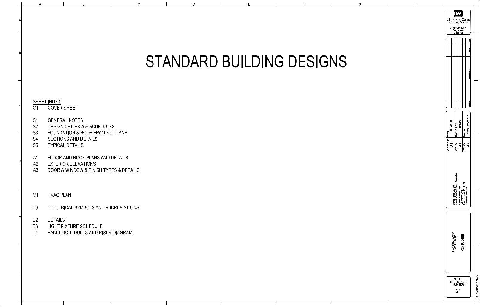
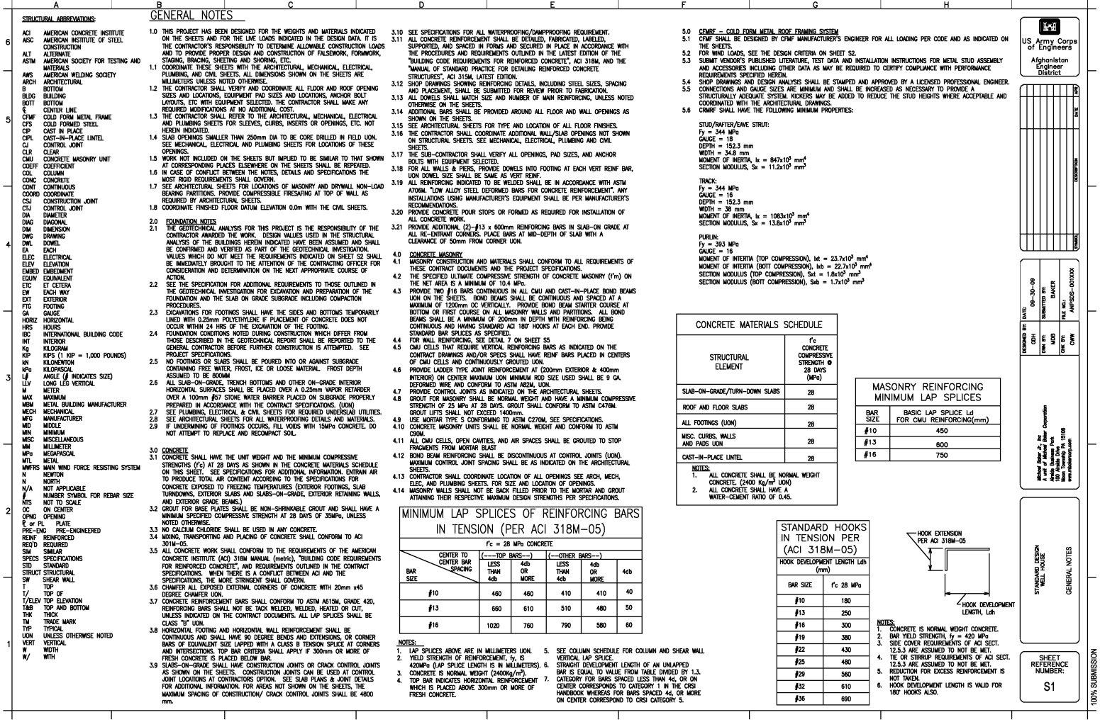
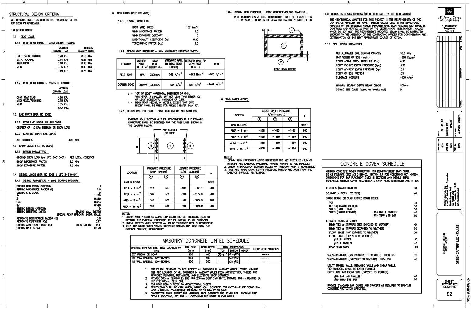
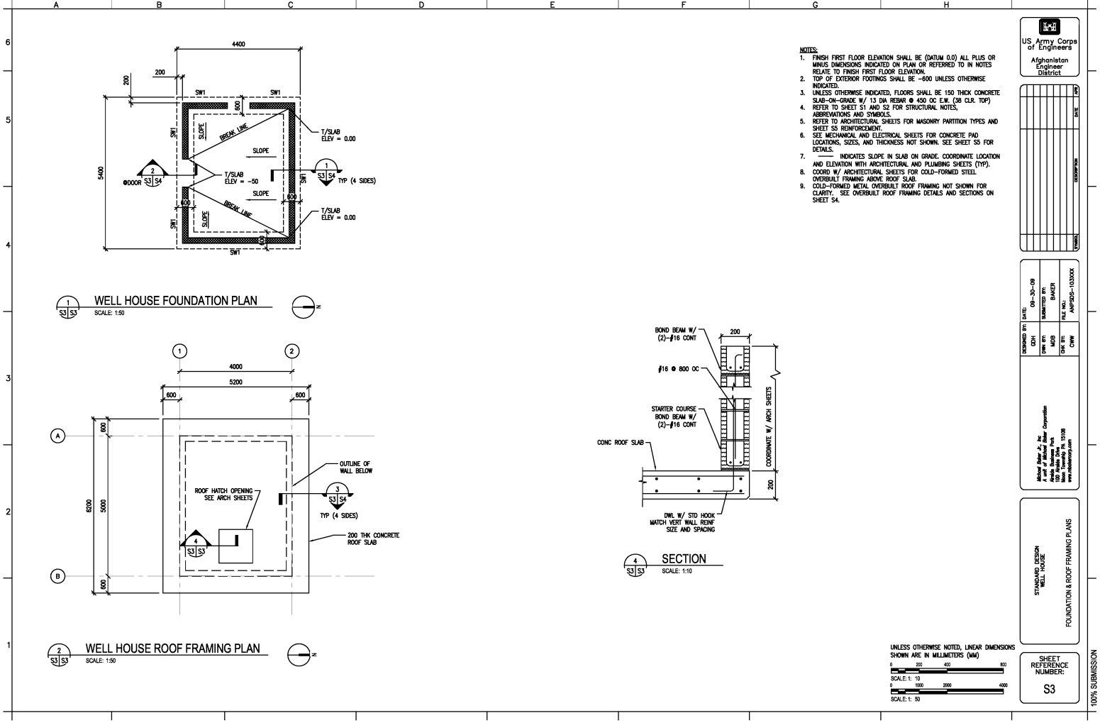
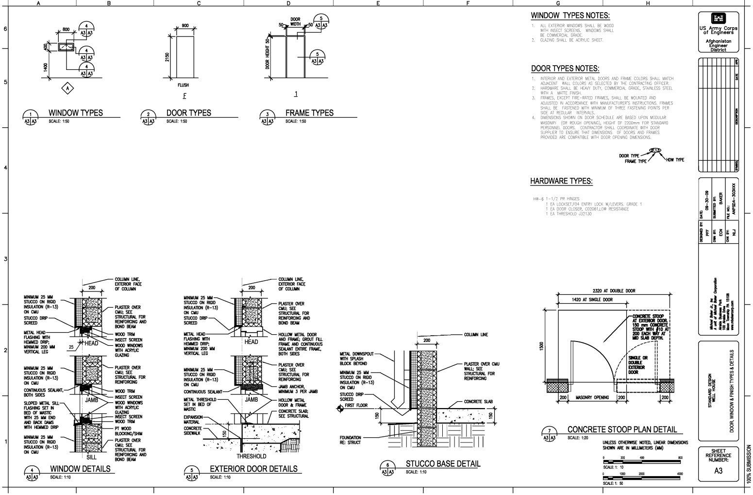
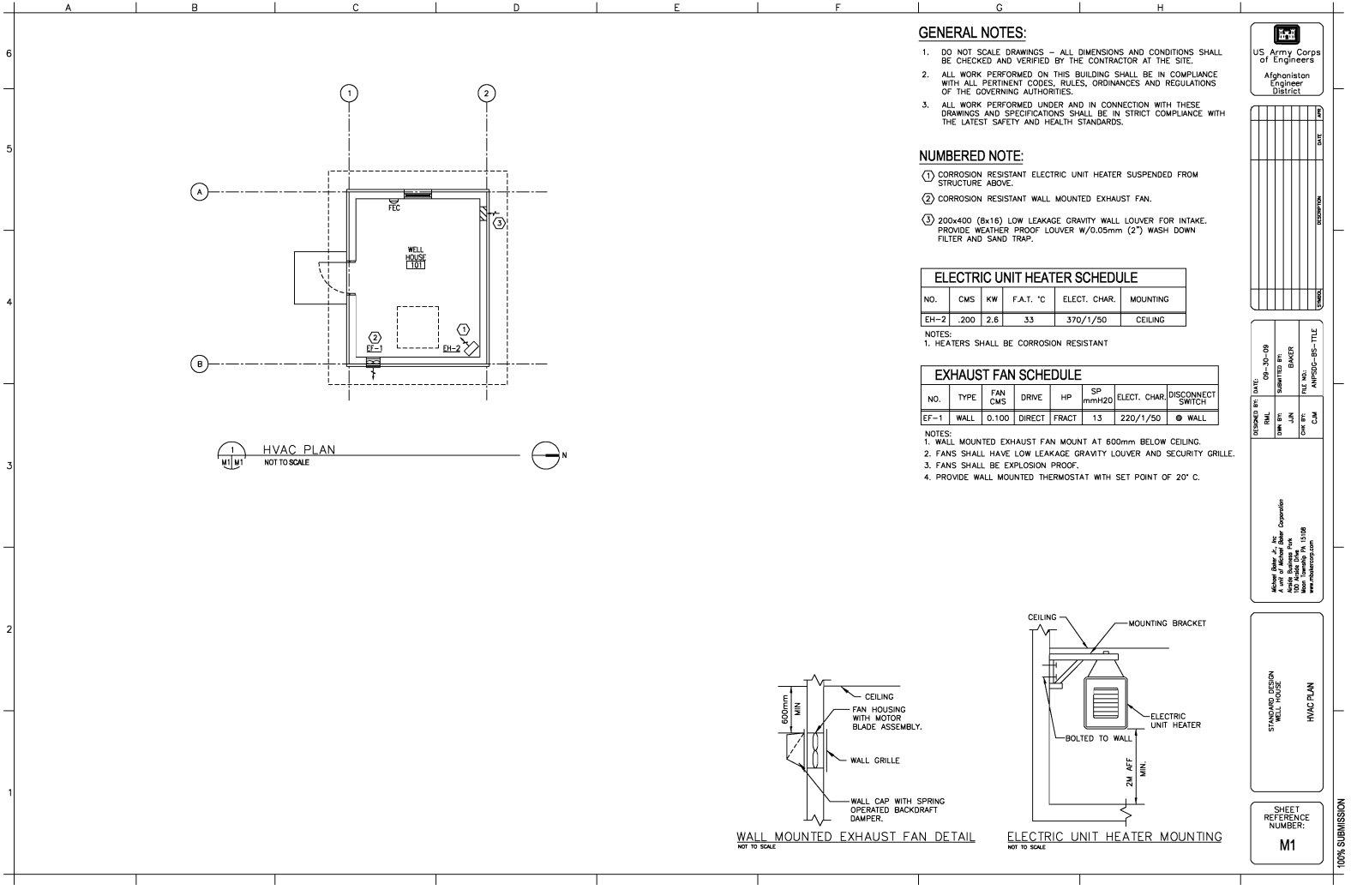
Construct one (1) Well House in accordance with the provided Standard drawings entitled “05 Well House”. Well
house shall be constructed at location of drilled water well as approximately illustrated on the Concept Site Plan.
2.5.9PUMP HOUSE
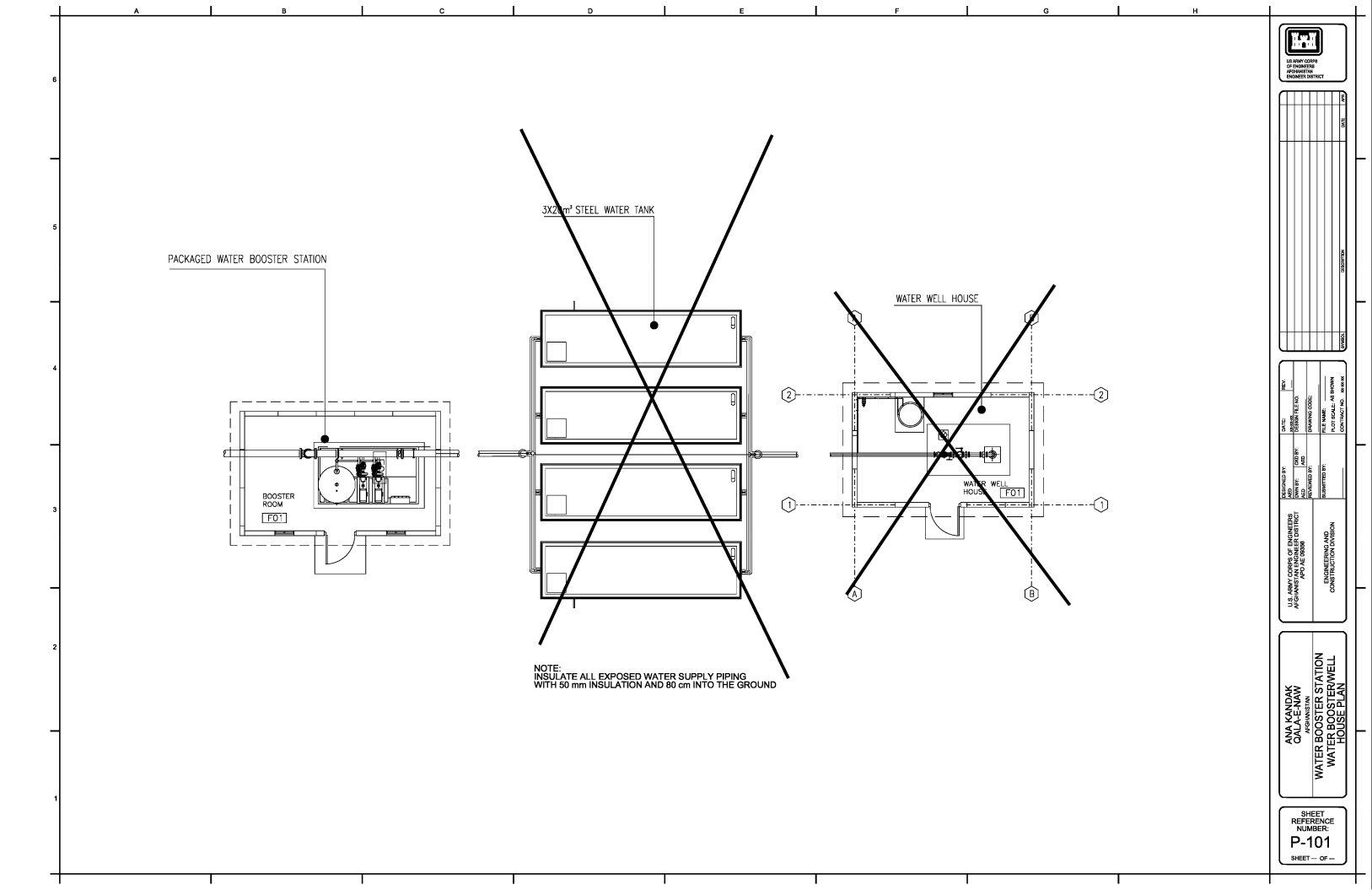
Construct one (1) Pump House in accordance with the provided Standard drawings entitled “05b Pump House” located as approximately illustrated on Concept Site Plan.
2.5.10MMT BUILDINGS
Construct two (2) Mobile Maintenance Team (MMT) Buildings in accordance with the provided Standard drawings titled “06 Mobile Maintenance Team Building”, located as approximately illustrated on the Concept Site plan.
W5J9LE-12-R-0024
Page 15 of 16
MMT Building #06b as denoted on Concept Site Plan shall be constructed according to standard drawings. MMT Building #06a as denoted on Concept Site Plan shall be constructed according to standard drawings with Toilet Room omitted from design, including all piping and fixtures.
2.5.11WAREHOUSE (SMALL)
Construct one (1) Warehouse, located as approximately illustrated on Concept Site Plan. Warehouse shall be constructed in accordance with the provided Standard Drawings titled “07 Warehouse, Small with DB Workshop, Eyewash” with the following additional requirements as is conceptually illustrated on Sht A1 of the drawings.
Design and Construct an “Enclosed Workshop” consisting of 200mm CMU interior partitions full height to
underside of structure with one steel door and heavy duty hardware in accordance with Section 01015.
Design and install one eyewash station in accordance with Section 01015 at approximate location as shown provided standard drawings.
2.5.12WAREHOUSE (LARGE)
Construct one (1) Warehouse located as approximately illustrated on Concept site plan. Construct warehouse in accordance with standard drawings titled “08 RMTC Storage (Warehouse Large)” with the following additional
requirements:
Design and construct chainlink fences extending full height to underside of structure with lockable gates enclosing two separate areas of 7m x 7m and and 4m x 4m respectively within warehouse. Both fenced areas shall be provided with 2m wide x 4m tall locakable gates.
Design and install one eyewash station in accordance with Section 01015.
2.5.13SECURE STORAGE BUILDING (ASP)
Construct one (1) Secure Storage Building (or Ammunition Supply Point, or ASP), located as approximately
illustrated on Concept Site Plan. Secure Storage Building shall be constructed in accordance with the provided Standard drawings titled “09 Secure Storage”. No other regularly-occupied buildings shall be located within a 45
meter standoff distance from the Secure Storage Buildings.
2.5.14LATRINE
Construct one (1) Latrine in accordance with the provided Standard Building Design drawings entitled “10 L01 -
Latrine Building Small”, located as approximately illustrated on Concept Site Plan. ”.
2.5.15GATE HOUSE
Construct one (1) Gate House in accordance with the provided Standard drawings titled “ 11Gate House”, located as
approximately illustrated on Concept Site Plan.
2.5.16GUARD SHACKS
Construct four (4) Guard Shacks in accordance with the provided Standard Building Design drawings titled
“12 Guard Shack”, located as approximately illustrated on Concept Site Plan.
2.5.17GUARD TOWERS
Construct four (4) Guard Towers, located in accordance with the Concept Site Plan. Guard Towers shall be constructed in accordance with the provided Standard Building Design drawings, entitled “ 13 Guard Tower”.
The design of the Guard Tower shall be flipped or mirrored for particular locations, so that its orientation matches to the Concept Site Plan.
W5J9LE-12-R-0024
Page 16 of 16
2.5.18TRASH COLLECTION POINT
Construct three (3) Trash Collection Points, located in accordance with the Concept Site Plan. Trash Collection Points shall be constructed in accordance with the provided Standard drawings titled “14 Trash Point”.
2.5.19CLOTHESLINE
Install two (2) clotheslines per standard drawing titled “ 22 Clothesline” at locations as approximately indicated on Concept Site plan.
3.0OPTIONAL ITEMS
3.1VEHICLE MAINTENANCE AND POL BUILDING
Construct one (1) Vehicle Maintenance and (1) POL building located as approximately illustrated per the Concept
Site Plan. The Vehicle Maintenance and POL buildings shall be constructed in accordance with provided standard drawings titled “23 Option V10 Vehicle Maintenance (3-Bay) and POL Building” with the following exceptions:
Contractor is to design and construct a loft space above the office areas as conceptually illustrated in the provided standard drawings. Loft space shall be provided with steel stairs and railing configured as per code and a continuous 2m tall fence along perimeter above maintenance area. Loft space shall also be divided into two (2) separate areas by fence with lockable gate.
Design and construct a Small Arms Repair room as conceptually illustrated in standard drawings consisting of 200mm CMU interior partitions full height to underside of structure with one steel door and heavy duty hardware in accordance with Section 01015.
Design and construct one eyewash station in accordance with Section 01015 at approximate location as shown provided standard drawings.
3.2WAREHOUSE (LARGE)
Construct one (1) Warehouse (Large) in accordance with the provided Standard drawings titled “08 RMTC Storage (Warehouse Large)” located as illustrated on Concept Site plan.
-- END OF SECTION –
(End of Summary of Changes)
05 B |
PUMP HOUSE |
P101 WATER BOOSTER STATION WATER BOOSTER/WELLHOUSE PLAN |
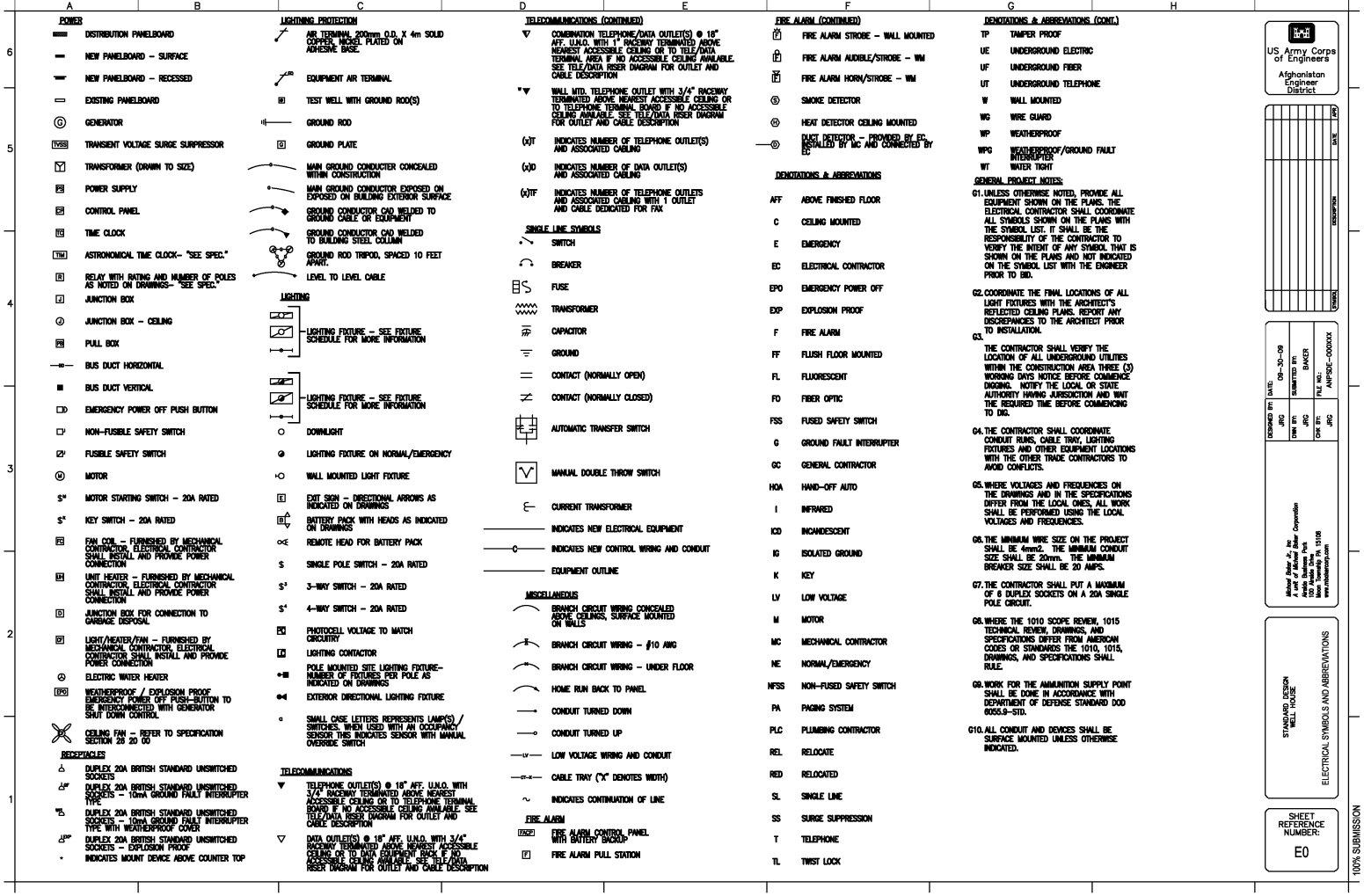
E101 BOOSTER STATION ELECTRICAL PLAN |
