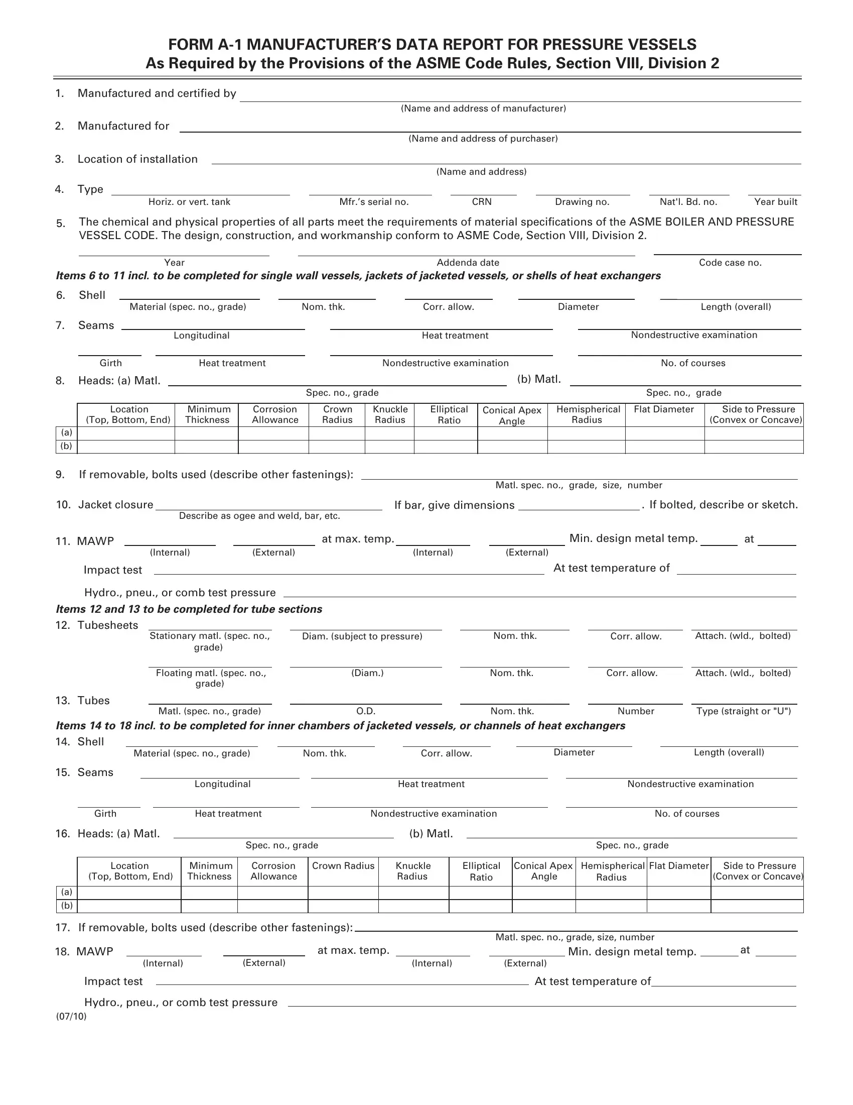
In the complex and critical realm of manufacturing pressure vessels, ensuring adherence to stringent standards is of paramount importance. The Form A-1 Manufacturer’s Data Report for Pressure Vessels embodies a fundamental document in this context, mandated by the provisions of the ASME Code Rules, Section VIII, Division 2. This form serves as a comprehensive record that details the construction, design, and specifications of pressure vessels, encompassing key aspects from the materials used to the fabrication techniques employed. It highlights the vessel's compliance with the acknowledged criteria laid out in the ASME BOILER AND PRESSURE VESSEL CODE, ensuring every component's chemical and physical properties meet the requisite specifications. The form meticulously documents a series of crucial elements, including but not limited to, the manufacturer’s and purchaser’s details, the vessel's type, dimensions, materials of construction, and design requirements such as minimum allowable working pressure at maximum temperature, ensuring a robust framework for safety and reliability. Furthermore, it incorporates certification sections that confirm both design and shop compliance, underscoring the rigorous inspection and testing processes that the vessel has undergone. This certification is not only a testament to the quality and standards adherence of the vessel but also a critical component in establishing trust and assurance in the pressure vessel's operational safety.
| Question | Answer |
|---|---|
| Form Name | Form A 1 |
| Form Length | 2 pages |
| Fillable? | No |
| Fillable fields | 0 |
| Avg. time to fill out | 30 sec |
| Other names | Matl, exchangers, incl, manufacturing data report example |
FORM
As Required by the Provisions of the ASME Code Rules, Section VIII, Division 2
1.Manufactured and certified by
(Name and address of manufacturer)
2.Manufactured for
(Name and address of purchaser)
3.Location of installation
(Name and address)
4.Type
Horiz. or vert. tank |
Mfr.’s serial no. |
CRN |
Drawing no. |
Nat'l. Bd. no. |
Year built |
5.The chemical and physical properties of all parts meet the requirements of material specifications of the ASME BOILER AND PRESSURE VESSEL CODE. The design, construction, and workmanship conform to ASME Code, Section VIII, Division 2.
Year |
Addenda date |
Code case no. |
Items 6 to 11 incl. to be completed for single wall vessels, jackets of jacketed vessels, or shells of heat exchangers
6.Shell
Material (spec. no., grade)Nom. thk.Corr. allow.DiameterLength (overall)
7. |
Seams |
|
|
|
|
|
|
|
|
|
|
|
|
|
|
|
|
|
|
|||
|
|
|
|
|
|
Longitudinal |
|
|
|
|
|
Heat treatment |
|
|
|
Nondestructive examination |
||||||
|
|
|
|
|
|
|
|
|
|
|
|
|
|
|
|
|
|
|
|
|
||
|
Girth |
Heat treatment |
|
|
|
Nondestructive examination |
|
|
|
No. of courses |
||||||||||||
8. |
Heads: (a) Matl. |
|
|
|
|
|
|
|
|
|
(b) Matl. |
|
|
|
|
|
||||||
|
|
|
|
|
|
|
|
Spec. no., grade |
|
|
|
|
|
|
|
Spec. no., |
grade |
|||||
|
|
|
|
|
|
|
|
|
|
|
|
|
|
|||||||||
|
Location |
Minimum |
Corrosion |
|
Crown |
Knuckle |
Elliptical |
Conical Apex |
|
Hemispherical |
Flat Diameter |
|
Side to Pressure |
|||||||||
|
(Top, Bottom, End) |
Thickness |
Allowance |
|
Radius |
Radius |
Ratio |
Angle |
|
|
Radius |
|
|
(Convex or Concave) |
||||||||
(a) |
|
|
|
|
|
|
|
|
|
|
|
|
|
|
|
|
|
|
|
|
|
|
|
|
|
|
|
|
|
|
|
|
|
|
|
|
|
|
|
|
|
|
|
|
|
(b) |
|
|
|
|
|
|
|
|
|
|
|
|
|
|
|
|
|
|
|
|
|
|
|
|
|
|
|
|
|
|
|
|
|
|
|
|
|
|
|
|
|
|
|
|
|
9.If removable, bolts used (describe other fastenings):
Matl. spec. no., grade, size, number
10. Jacket closure |
|
If bar, give dimensions |
|
. If bolted, describe or sketch. |
Describe as ogee and weld, bar, etc.
11. |
MAWP |
|
|
|
|
|
|
|
|
|
|
|
|
|
|
at max. temp. |
|
|
|
|
|
|
|
|
|
|
|
|
|
|
|
|
Min. design metal temp. |
|
|
at |
|
|
|||||||||||||||
|
|
|
|
|
(Internal) |
|
(External) |
|
|
|
|
|
|
|
|
(Internal) |
|
|
|
|
|
(External) |
|
|
|
|
|
|
|
|
|
|
|
|
|
|
|
|
|||||||||||||||
|
Impact test |
|
|
|
|
|
|
|
|
|
|
|
|
|
|
|
|
|
|
|
|
|
|
|
|
|
|
|
|
|
|
|
|
At test temperature of |
|
|
|
|
|
|
|
|
|||||||||||
|
Hydro., pneu., or comb test pressure |
|
|
|
|
|
|
|
|
|
|
|
|
|
|
|
|
|
|
|
|
|
|
|
|
|
|
|
|
|
|
|
|
|
|
|
|
|
|
||||||||||||||
Items 12 and 13 to be completed for tube sections |
|
|
|
|
|
|
|
|
|
|
|
|
|
|
|
|
|
|
|
|
|
|
|
|
|
|
|
|
|
|
|||||||||||||||||||||||
12. |
Tubesheets |
|
|
|
|
|
|
|
|
|
|
|
|
|
|
|
|
|
|
|
|
|
|
|
|
|
|
|
|
|
|
|
|
|
|
|
|
|
|
|
|
|
|
|
|
|
|
|
|
||||
|
|
|
|
|
Stationary matl. (spec. no., |
Diam. (subject to pressure) |
|
|
|
|
Nom. thk. |
|
|
|
|
Corr. allow. |
|
|
Attach. (wld., |
bolted) |
|||||||||||||||||||||||||||||||||
|
|
|
|
|
|
|
|
grade) |
|
|
|
|
|
|
|
|
|
|
|
|
|
|
|
|
|
|
|
|
|
|
|
|
|
|
|
|
|
|
|
|
|
|
|
|
|
|
|
|
|
|
|
|
|
|
|
|
|
|
|
|
|
|
|
|
|
|
|
|
|
|
|
|
|
|
|
|
|
|
|
|
|
|
|
|
|
|
|
|
|
|
|
|
|
|
|
|
|
|
|
||||||||
|
|
|
|
|
|
Floating matl. (spec. no., |
|
|
|
(Diam.) |
|
|
|
|
|
|
|
Nom. thk. |
|
|
|
|
Corr. allow. |
|
|
Attach. (wld., |
bolted) |
||||||||||||||||||||||||||
|
|
|
|
|
|
|
|
grade) |
|
|
|
|
|
|
|
|
|
|
|
|
|
|
|
|
|
|
|
|
|
|
|
|
|
|
|
|
|
|
|
|
|
|
|
|
|
|
|
|
|
|
|
|
|
13. |
Tubes |
|
|
|
|
|
|
|
|
|
|
|
|
|
|
|
|
|
|
|
|
|
|
|
|
|
|
|
|
|
|
|
|
|
|
|
|
|
|
|
|
|
|
|
|
|
|
|
|
|
|||
|
|
|
|
|
|
Matl. (spec. no., grade) |
|
|
|
O.D. |
|
|
|
|
|
|
|
Nom. thk. |
|
|
|
|
Number |
|
|
Type (straight or "U") |
|||||||||||||||||||||||||||
Items 14 to 18 incl. to be completed for inner chambers of jacketed vessels, or channels of heat exchangers |
|
|
|
|
|
|
|
|
|||||||||||||||||||||||||||||||||||||||||||||
14. |
Shell |
|
|
|
|
|
|
|
|
|
|
|
|
|
|
|
|
|
|
|
|
|
|
|
|
|
|
|
|
|
|
|
|
|
|
|
|
|
|
|
|
|
|
|
|
|
|
|
|
||||
|
|
|
Material (spec. no., grade) |
Nom. thk. |
|
Corr. allow. |
|
|
|
|
|
Diameter |
|
|
Length (overall) |
||||||||||||||||||||||||||||||||||||||
15. |
Seams |
|
|
|
|
|
|
|
|
|
|
|
|
|
|
|
|
|
|
|
|
|
|
|
|
|
|
|
|
|
|
|
|
|
|
|
|
|
|
|
|
|
|
|
|
|
|
|
|||||
|
|
|
|
|
|
|
|
Longitudinal |
|
|
|
|
|
|
|
Heat treatment |
|
|
|
|
|
|
|
|
|
Nondestructive examination |
|
|
|||||||||||||||||||||||||
|
|
|
|
|
|
|
|
|
|
|
|
|
|
|
|
|
|
|
|
|
|
|
|
|
|
|
|
|
|
||||||||||||||||||||||||
|
Girth |
|
Heat treatment |
|
|
|
Nondestructive examination |
|
|
|
|
|
|
|
|
|
|
|
No. of courses |
|
|
||||||||||||||||||||||||||||||||
16. |
Heads: (a) Matl. |
|
|
|
|
|
|
|
|
|
|
|
|
|
|
|
|
|
|
(b) Matl. |
|
|
|
|
|
|
|
|
|
|
|
|
|
|
|
|
|
|
|
|
|
|
|
|
|
|
|||||||
|
|
|
|
|
|
|
|
|
|
|
Spec. no., grade |
|
|
|
|
|
|
|
|
|
|
|
|
|
|
|
|
|
|
Spec. no., grade |
|
|
|
|
|
|
|
|
|||||||||||||||
|
|
|
|
|
|
|
|
|
|
|
|
|
|
|
|
|
|
||||||||||||||||||||||||||||||||||||
|
Location |
|
Minimum |
|
Corrosion |
|
|
Crown Radius |
|
Knuckle |
|
Elliptical |
|
Conical Apex |
Hemispherical |
Flat Diameter |
Side to Pressure |
||||||||||||||||||||||||||||||||||||
|
(Top, Bottom, End) |
|
Thickness |
|
Allowance |
|
|
|
|
|
|
|
Radius |
|
|
Ratio |
|
|
Angle |
|
Radius |
|
|
|
|
|
(Convex or Concave) |
||||||||||||||||||||||||||
|
|
|
|
|
|
|
|
|
|
|
|
|
|
|
|
|
|
|
|
|
|
|
|
|
|
|
|
|
|
|
|
|
|
|
|
|
|
|
|
|
|
|
|
|
|
|
|
|
|
|
|
|
|
(a) |
|
|
|
|
|
|
|
|
|
|
|
|
|
|
|
|
|
|
|
|
|
|
|
|
|
|
|
|
|
|
|
|
|
|
|
|
|
|
|
|
|
|
|
|
|
|
|
|
|
|
|
|
|
|
|
|
|
|
|
|
|
|
|
|
|
|
|
|
|
|
|
|
|
|
|
|
|
|
|
|
|
|
|
|
|
|
|
|
|
|
|
|
|
|
|
|
|
|
|
|
|
|
|
|
|
|
|
(b) |
|
|
|
|
|
|
|
|
|
|
|
|
|
|
|
|
|
|
|
|
|
|
|
|
|
|
|
|
|
|
|
|
|
|
|
|
|
|
|
|
|
|
|
|
|
|
|
|
|
|
|
|
|
|
|
|
|
|
|
|
|
|
|
|
|
|
|
|
|
|
|
|
|
|
|
|
|
|
|
|
|
|
|
|
|
|
|
|
|
|
|
|
|
|
|
|
|
|
|
|
|
|
|
|
|
|
|
17. If removable, bolts used (describe other fastenings):
18. MAWP
(Internal) |
(External) |
Impact test
Hydro., pneu., or comb test pressure
|
|
Matl. spec. no., grade, size, number |
|
|
|
||
|
|
|
Min. design metal temp. |
|
at |
|
|
(Internal) |
|
(External) |
|
|
|
||
|
|
At test temperature of |
|
|
|
|
|
(07/10)
FORM
Items below to be completed for all vessels where applicable. 19. Nozzles inspection and safety valve openings
Purpose
(lnlet, Outlet, Drain, etc.)
No.
Diam. or Size
Type
Material
Nom. Thk.
Reinforcement Material
How Attached
Location
20. Support Skirt |
|
Lugs |
|
Legs |
|
|
Other |
|
Attached |
|
|
|
|
||||||||||
|
Yes or no |
|
|
|
|
No. |
|
|
|
No. |
|
|
|
Describe |
|
|
Where and how |
|
|
||||
21. Service: Fatigue analysis required |
|
and |
|
|
|
|
|
|
|
|
|
|
|
||||||||||
|
|
|
|
|
|
Yes or no |
|
|
|
|
|
|
|
Describe contents or service |
|
|
|||||||
|
|
|
|
|
|
|
|
|
|
|
|
|
|
|
|
|
|
|
|
|
|
|
|
Remarks: |
|
|
|
|
|
|
|
|
|
|
|
|
|
|
|
|
|
|
|
|
|
|
|
|
|
|
|
|
|
|
|
|
|
|
|
|
|
|
|
|
|
|
|
|
|||
|
|
|
|
|
|
|
|
|
|
|
|
|
|
|
|
|
|
|
|
|
|||
|
|
|
|
|
|
|
|
|
|
|
CERTIFICATION OF DESIGN |
|
|
|
|
|
|
|
|||||
Users Design Specification on file at |
|
|
|
|
|
|
|
|
|
|
|
|
|
|
|
|
|
|
|
|
|
||
Manufacturer’s Design Report on file at |
|
|
|
|
|
|
|
|
|
|
|
|
|
|
|
|
|
|
|||||
User’s Design Specification certified by |
|
|
|
|
|
|
PE State |
|
|
|
Reg. No. |
|
|
|
|||||||||
Manufacturer’s Design Report certified by |
|
|
|
|
|
PE State |
|
|
Reg. No. |
|
|
||||||||||||
|
|
|
|
|
|
|
|
|
|
|
|
|
|
|
|
|
|
|
|
|
|
|
|
CERTIFICATE OF SHOP COMPLIANCE
We certify that the statements in this report are correct and that all details of design, material, construction, and workmanship of this vessel conforms to the ASME Code for Pressure Vessels, Section VIII, Division 2.
“U2” Certificate of |
Authorization No. |
|
|
expires |
|
|
|
|
|||
Date |
|
Co. name |
|
|
|
|
Signed |
|
|||
|
|
|
|
|
|
|
|
|
|
|
|
|
|
|
|
|
|
Manufacturer |
|
Representative |
|
||
|
|
|
|
|
|
|
|
|
|||
|
|
|
|
|
CERTIFICATE OF SHOP INSPECTION |
|
|
|
|||
Vessel made by |
|
|
|
at |
|
|
|
I, the undersigned, holding a valid commission issued by the National |
Board of Boiler and Pressure Vessel Inspectors and/or the |
||||||
Province of |
|
and employed by |
|
|
of |
||
|
|
|
|
|
|
|
|
have inspected the pressure vessel described in this Manufacturer’s Data Report on |
|||||||
State or
,
,
and state that, to the best of my knowledge and belief, the Manufacturer has constructed this pressure vessel in accordance with ASME Code, Section VIII, Division 2. By signing this certificate neither the Inspector nor his employer makes any warranty, expressed or implied, concerning the pressure vessel described in this Manufacturer’s’ Data Report. Furthermore, neither the Inspector nor his employer shall be liable in any manner for any personal injury or property damage or a loss of any kind arising from or connected with this inspection.
Date |
|
Signed |
Commissions |
||
|
|
|
Authorized Inspector |
|
Nat’I. Board (incl. Endorsements), State, Prov., and No. |
CERTIFICATE OF FIELD ASSEMBLY COMPLIANCE
We certify that the field assembly construction of all parts of this vessel conforms with the requirements of Section VIII, Division 2 of the ASME BOILER AND PRESSURE VESSEL CODE.
“U2” Certificate of |
Authorization No. |
|
|
expires |
|
|
|
||
Date |
|
|
Co. name |
|
|
|
Signed |
|
|
|
|
|
|
|
|
||||
|
|
|
|
|
Assembler that certified and constructed field assembly |
Representative |
|||
CERTIFICATE OF FIELD ASSEMBLY INSPECTION
I, the undersigned, holding a valid commission issued by the National Board of Boiler and Pressure Vessel Inspectors and/or the State or
Province of |
|
and employed by |
|
of |
have compared the statements in this Manufacturer’s Data Report with the described pressure vessel and state that parts referred to as data items
not included in the certificate of shop inspection, have been inspected by me and that, to the best of my knowledge and belief, the
Manufacturer has constructed and assembled this pressure vessel in accordance with the ASME Code, Section. VIII, Division 2.
The described vessel was inspected and subjected to a hydrostatic test of.
By signing this certificate neither the Inspector nor his employer makes any warranty, expressed or implied, concerning the pressure vessel described in this Manufacturer’s Data Report. Furthermore, neither the Inspector nor his employer shall be liable in any manner for any personal injury or property damage or a loss of any kind arising from or connected with this inspection.
Date |
|
Signed |
|
Commissions |
|
|
Authorized Inspector |
Nat’I. Board (incl. Endorsements), State, Prov., and No. |
|||
|
|
|
|
(07/10)