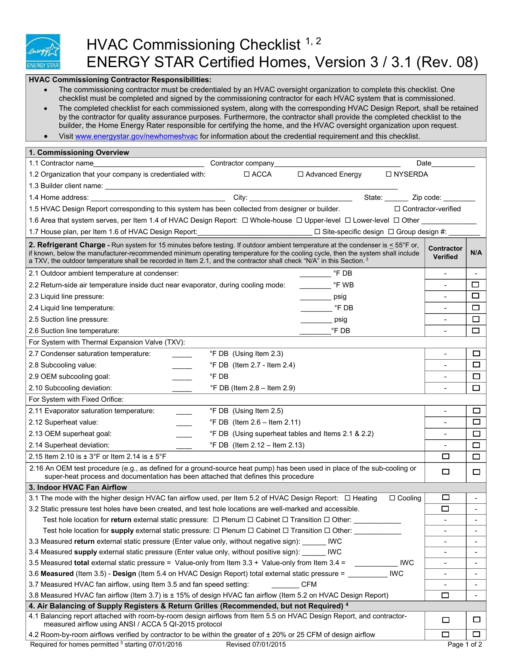
HVAC Commissioning Checklist 1, 2
ENERGY STAR Certified Homes, Version 3 / 3.1 (Rev. 08)
HVAC Commissioning Contractor Responsibilities:
The commissioning contractor must be credentialed by an HVAC oversight organization to complete this checklist. One checklist must be completed and signed by the commissioning contractor for each HVAC system that is commissioned.
The completed checklist for each commissioned system, along with the corresponding HVAC Design Report, shall be retained by the contractor for quality assurance purposes. Furthermore, the contractor shall provide the completed checklist to the builder, the Home Energy Rater responsible for certifying the home, and the HVAC oversight organization upon request.
Visit www.energystar.gov/newhomeshvac for information about the credential requirement and this checklist.
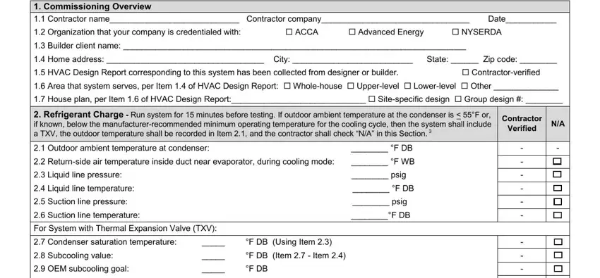
1. Commissioning Overview
|
1.1 |
Contractor name____________________________ |
Contractor company________________________________ |
Date___________ |
|
|
1.2 |
Organization that your company is credentialed with: |
|
ACCA |
|
Advanced Energy |
NYSERDA |
|
|
|
|
|
|
|
1.3 |
Builder client name: __________________________________________________________________________ |
|
|
|
|
|
|
|
|
|
|
1.4 |
Home address: __________________________________ |
City: __________________________ |
State: ______ Zip code: ________ |
|
|
1.5 |
HVAC Design Report corresponding to this system has been collected from designer or builder. |
|
|
Contractor-verified |
|
|
|
|
|
1.6 |
Area that system serves, per Item 1.4 of HVAC Design Report: Whole-house |
Upper-level |
Lower-level Other ______________ |
|
|
1.7 |
House plan, per Item 1.6 of HVAC Design Report:_____________________________ Site-specific design |
Group design #: ________ |
|
|
|
|
|
|
|
|
|
|
|
|
2. Refrigerant Charge - Run system for 15 minutes before testing. If outdoor ambient temperature at the condenser is < 55°F or, |
|
|
Contractor |
|
|
N/A |
|
|
|
if known, below the manufacturer-recommended minimum operating temperature for the cooling cycle, then the system shall include |
|
|
|
|
|
|
|
|
Verified |
|
|
|
|
|
a TXV, the outdoor temperature shall be recorded in Item 2.1, and the contractor shall check “N/A” in this Section. 3 |
|
|
|
|
|
|
|
|
|
|
|
|
|
|
|
|
|
|
|
|
|
2.1 |
Outdoor ambient temperature at condenser: |
|
|
|
________ °F DB |
|
|
|
|
|
- |
|
- |
|
|
|
|
|
|
|
|
|
|
|
|
|
|
|
|
|
2.2 |
Return-side air temperature inside duct near evaporator, during cooling mode: |
________ °F WB |
|
|
|
|
|
- |
|
|
|
|
|
|
|
|
|
|
|
|
|
|
|
|
|
|
|
|
|
|
|
2.3 |
Liquid line pressure: |
|
|
|
|
________ psig |
|
|
|
|
|
- |
|
|
|
|
|
|
|
|
|
|
|
|
|
|
|
|
|
|
|
|
|
|
|
2.4 |
Liquid line temperature: |
|
|
|
|
________ °F DB |
|
|
|
|
|
- |
|
|
|
|
|
|
|
|
|
|
|
|
|
|
|
|
|
|
|
|
|
|
|
2.5 |
Suction line pressure: |
|
|
|
|
________ psig |
|
|
|
|
|
- |
|
|
|
|
|
|
|
|
|
|
|
|
|
|
|
|
|
|
|
|
|
|
|
2.6 |
Suction line temperature: |
|
|
|
|
________°F DB |
|
|
|
|
|
- |
|
|
|
|
|
|
|
|
|
|
|
|
|
|
|
|
|
|
|
|
|
|
|
For System with Thermal Expansion Valve (TXV): |
|
|
|
|
|
|
|
|
|
|
|
|
|
|
|
|
|
|
|
|
|
|
|
|
|
|
|
|
|
|
|
|
|
|
|
2.7 |
Condenser saturation temperature: |
_____ |
°F DB |
(Using Item 2.3) |
|
|
|
|
|
|
|
- |
|
|
|
|
|
|
|
|
|
|
|
|
|
|
|
|
|
|
|
|
|
|
|
2.8 |
Subcooling value: |
_____ |
°F DB |
(Item 2.7 - Item 2.4) |
|
|
|
|
|
|
|
- |
|
|
|
|
|
|
|
|
|
|
|
|
|
|
|
|
|
|
|
|
|
|
|
|
2.9 |
OEM subcooling goal: |
_____ |
°F DB |
|
|
|
|
|
|
|
|
|
- |
|
|
|
|
|
|
|
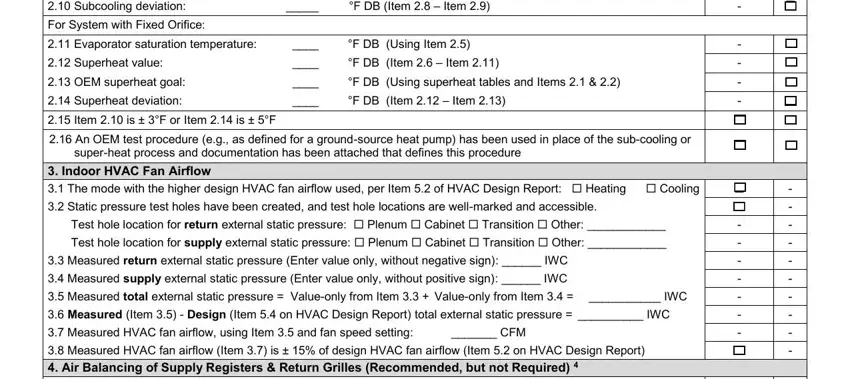
°F DB (Item 2.8 – Item 2.9) |
|
|
|
|
|
|
|
|
|
|
|
|
|
2.10 Subcooling deviation: |
_____ |
|
|
|
|
|
|
|
- |
|
|
|
|
|
|
|
|
|
|
|
|
|
|
|
|
|
|
|
|
|
|
|
|
For System with Fixed Orifice: |
|
|
|
|
|
|
|
|
|
|
|
|
|
|
|
|
|
|
|
|
|
|
|
|
|
|
|
|
|
|
|
|
|
|
|
2.11 Evaporator saturation temperature: |
____ |
°F DB |
(Using Item 2.5) |
|
|
|
|
|
|
|
- |
|
|
|
|
|
|
|
|
(Item 2.6 – Item 2.11) |
|
|
|
|
|
|
|
|
|
|
|
|
2.12 Superheat value: |
____ |
°F DB |
|
|
|
|
|
|
- |
|
|
|
|
|
|
|
|
|
|
|
|
|
|
|
|
|
|
|
2.13 OEM superheat goal: |
____ |
°F DB |
(Using superheat tables and Items 2.1 & 2.2) |
|
|
|
|
- |
|
|
|
|
|
|
|
|
(Item 2.12 – Item 2.13) |
|
|
|
|
|
|
|
|
|
|
|
|
2.14 Superheat deviation: |
____ |
°F DB |
|
|
|
|
|
|
- |
|
|
|
|
|
2.15 Item 2.10 is ± 3°F or Item 2.14 is ± 5°F |
|
|
|
|
|
|
|
|
|
|
|
|
|
|
|
|
|
|
|
|
|
|
|
|
|
|
|
2.16 An OEM test procedure (e.g., as defined for a ground-source heat pump) has been used in place of the sub-cooling or |
|
|
|
|
|
|
|
|
|
super-heat process and documentation has been attached that defines this procedure |
|
|
|
|
|
|
|
|
|
|
|
|
|
|
|
|
|
|
|
|
|
|
|
|
|
|
|
|
|
|
|
|
|
|
|
|
|
|
|
|
|
|
3. Indoor HVAC Fan Airflow |
|
|
|
|
|
|
|
|
|
|
|
|
|
|
|
|
|
|
3.1 |
The mode with the higher design HVAC fan airflow used, per Item 5.2 of HVAC Design Report: |
Heating |
Cooling |
|
|
- |
|
|
|
|
|
|
|
|
|
|
|
|
|
|
3.2 |
Static pressure test holes have been created, and test hole locations are well-marked and accessible. |
|
|
|
|
|
- |
|
|
|
|
Test hole location for return external static pressure: Plenum Cabinet Transition Other: ____________ |
|
|
|
|
|
|
|
|
|
|
|
|
|
- |
|
- |
|
|
|
|
Test hole location for supply external static pressure: Plenum Cabinet Transition Other: ____________ |
|
|
|
|
|
|
|
|
|
|
|
|
|
- |
|
- |
|
|
|
|
|
|
|
|
|
|
|
|
|
|
|
|
|
3.3 |
Measured return external static pressure (Enter value only, without negative sign): ______ IWC |
|
|
|
|
|
|
- |
|
- |
|
|
|
|
|
|
|
|
|
|
|
|
|
|
|
|
|
3.4 |
Measured supply external static pressure (Enter value only, without positive sign): ______ IWC |
|
|
|
|
|
|
- |
|
- |
|
|
|
|
|
|
|
|
|
|
|
|
|
|
|
|
3.5 |
Measured total external static pressure = |
Value-only from Item 3.3 + Value-only from Item 3.4 = |
___________ IWC |
|
|
|
- |
|
- |
|
|
|
|
|
|
|
|
|
|
|
|
|
|
3.6 |
Measured (Item 3.5) - Design (Item 5.4 on HVAC Design Report) total external static pressure = __________ IWC |
|
|
|
- |
|
- |
|
|
|
|
|
|
|
|
|
|
|
|
|
|
|
|
|
|
3.7 |
Measured HVAC fan airflow, using Item 3.5 and fan speed setting: |
_______ CFM |
|
|
|
|
|
|
- |
|
- |
|
|
|
|
|
|
|
|
|
|
|
|
|
3.8 |
Measured HVAC fan airflow (Item 3.7) is ± 15% of design HVAC fan airflow (Item 5.2 on HVAC Design Report) |
|
|
|
|
- |
|
|
|
|
|
|
|
|
|
|
|
|
|
|
|
|
4. Air Balancing of Supply Registers & Return Grilles (Recommended, but not Required) 4 |
|
|
|
|
|
|
|
|
|
|
|
|
4.1 |
Balancing report attached with room-by-room design airflows from Item 5.5 on HVAC Design Report, and contractor- |
|
|
|
|
|
|
|
|
|
measured airflow using ANSI / ACCA 5 QI-2015 protocol |
|
|
|
|
|
|
|
|
|
|
|
|
|
|
|
|
|
|
|
|
|
|
|
|
|
|
|
|
|
4.2 |
Room-by-room airflows verified by contractor to be within the greater of ± 20% or 25 CFM of design airflow |
|
|
|
|
|
|
|
|
|
|
|
|
|
|
|
|
|
|
|
|
|
|
Required for homes permitted 5 starting 07/01/2016 |
Revised 07/01/2015 |
|
|
|
|
|
|
|
Page 1 of 2 |
|
HVAC Commissioning Checklist 1, 2
ENERGY STAR Certified Homes, Version 3 / 3.1 (Rev. 08)
Footnotes
1.This Checklist is designed to align with the requirements of ANSI / ACCA’s 5 QI-2015 protocol, thereby improving the performance of HVAC equipment in new homes when compared to homes built to minimum code. However, these features alone cannot prevent all ventilation, indoor air quality, and HVAC problems (e.g., those caused by a lack of maintenance by occupants). Therefore, this Checklist is not a guarantee of proper ventilation, indoor air quality, or HVAC performance.
This Checklist applies to split air conditioners, unitary air conditioners, air-source heat pumps, and water-source (i.e., geothermal) heat pumps up to 65 kBtuh with forced-air distribution systems (i.e., ducts) and to furnaces up to 225 kBtuh with forced-air distribution systems (i.e., ducts). All other permutations of equipment (e.g., boilers, mini-split / multi-split systems) and distribution systems are exempt.
2.For a home certified in the State of ID, MT, OR, or WA, the following alternatives and exemptions apply:
a.For a home with an air-source heat pump up to 65 kBtuh with a forced-air distribution system (i.e., ducts), the contractor is permitted to complete the 2011 PTCS® Commissioned Heat Pump Certificate and Startup Form in lieu of this Checklist.
b.For a home with a split air conditioner or unitary air conditioner up to 65 kBtuh with a forced-air distribution system (i.e., ducts), the contractor is permitted to complete the Northwest Central AC Commissioning & Startup Form in lieu of this Checklist.
c.For a home in a location with < 600 CDD, the completion of this Checklist is recommended, but not required.
3.Either factory-installed or field-installed TXV’s may be used. For field-installed TXV’s, ensure that sensing bulbs are insulated and tightly clamped to the vapor line with good linear thermal contact at the recommended orientation, usually 4 or 8 o’clock.
4.Air balancing of supply registers and return grilles is highly recommended to improve the performance of the HVAC system and comfort of the occupants, but is not required at this time for certification. When air balancing is completed, balancing dampers or proper duct sizing shall be used instead of looped or coiled ductwork to limit flow to diffusers. When balancing dampers are used, they shall be located at the trunk to limit noise unless the trunk will not be accessible when the balancing process is conducted. In such cases, Opposable Blade Dampers (OBD) or dampers located in the duct boot are permitted to be used.
5.This Revision of the HVAC Commissioning Checklist is required to certify all homes permitted after 07/01/2016, but is allowed to be used for any home permitted or completed prior to this date. The Home Energy Rater certifying the home may define the ‘permit date’ as either the date that the permit was issued or the date of the contract on the home. In cases where permit or contract dates are not available, Providers have discretion to estimate permit dates based on other construction schedule factors.
Required for homes permitted 5 starting 07/01/2016 |
Revised 07/01/2015 |
Page 2 of 2 |