In the realm of electronic components that play a critical role in converting light into electrical signals, the OP950 PIN Silicon Photodiode stands out with its unique features and broad applicability. Introduced in the June 1996 product bulletin by Optek Technology, Inc., this photodiode is designed to capture spectral responses across visible to infrared light wavelengths, thanks to its clear epoxy packaging. Its wide receiving angle ensures consistent reception over a broad area, while its side-looking package caters to space-constrained applications, making it an ideal choice for integration into various electronic assemblies. The OP950's compatibility with Optek’s series of infrared emitting diodes, along with its fast switching time, underlines its utility in creating efficient optical coupling, crucial for high-speed data transmission and sensing applications. A highlight in its design includes the ability to withstand substantial environmental and operational stresses, demonstrated by its absolute maximum ratings which encompass a reverse breakdown voltage of 60V and a significant tolerance to temperature variations and soldering heat. These attributes, along with the detailed electrical characteristics provided by Optek, such as reverse light and dark current specifications, and performance curves covering aspects from light current vs. irradiance to switching times, position the OP950 as a robust and versatile component in the field of optoelectronics.
| Question | Answer |
|---|---|
| Form Name | Op950 Form |
| Form Length | 2 pages |
| Fillable? | No |
| Fillable fields | 0 |
| Avg. time to fill out | 30 sec |
| Other names | op950 fedex, op950 fed ex form, op 950a, fedex hazardous materials certification form op 950 |
Product Bulletin OP950
June 1996
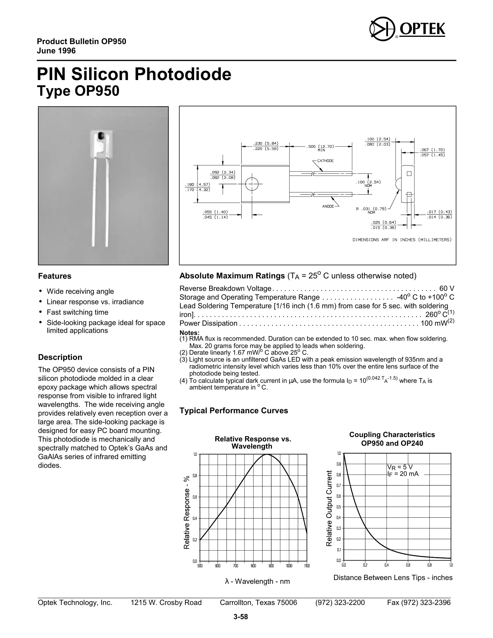
PIN Silicon Photodiode
Type OP950
Features
∙Wide receiving angle
∙Linear response vs. irradiance
∙Fast switching time
∙
Description
The OP950 device consists of a PIN silicon photodiode molded in a clear epoxy package which allows spectral response from visible to infrared light wavelengths. The wide receiving angle provides relatively even reception over a large area. The
Absolute Maximum Ratings (TA = 25o C unless otherwise noted)
Reverse Breakdown Voltage. . . . . . . . . . . . . . . . . . . . . . . . . . . . . . . . . . . . . . . . . 60 V Storage and Operating Temperature Range . . . . . . . . . . . . . . . . . .
Lead Soldering Temperature [1/16 inch (1.6 mm) from case for 5 sec. with soldering iron]. . . . . . . . . . . . . . . . . . . . . . . . . . . . . . . . . . . . . . . . . . . . . . . . . . . . . . . . . 260o C(1) Power Dissipation . . . . . . . . . . . . . . . . . . . . . . . . . . . . . . . . . . . . . . . . . . . . . 100 mW(2)
Notes:
(1)RMA flux is recommended. Duration can be extended to 10 sec. max. when flow soldering. Max. 20 grams force may be applied to leads when soldering.
(2)Derate linearly 1.67 mW/o C above 25o C.
(3)Light source is an unfiltered GaAs LED with a peak emission wavelength of 935nm and a radiometric intensity level which varies less than 10% over the entire lens surface of the photodiode being tested.
(4)To calculate typical dark current in μA, use the formula ID = 10(0.042
Typical Performance Curves
Relative Response vs. |
Coupling Characteristics |
|||
OP950 and OP240 |
||||
Wavelength |
||||
|
|
|
||
|
|
|
|
|
|
|
VR = 5 V |
||
|
|
IF = 20 mA |
|
|
|
|
λ - Wavelength - nm |
Distance Between Lens Tips - inches |
|
|
|
|
|
|
Optek Technology, Inc. |
1215 W. Crosby Road |
Carrollton, Texas 75006 |
(972) |
Fax (972) |
|
|
|
|
|
Type OP950
Electrical Characteristics (TA = 25o C unless otherwise noted) |
|
|
|
|
||
SYMBOL |
PARAMETER |
MIN TYP |
MAX |
UNITS |
|
TEST CONDITIONS |
IL |
Reverse Light Current |
8 |
18 |
μ |
VR = 5 V, Ee = 1 mW/cm2(3) |
|
A |
|
|
||||
ID |
Reverse Dark Current |
1 |
60 |
nA |
VR = 30 |
V, Ee = 0 |
V(BR) |
Reverse Breakdown Voltage |
60 |
|
V |
IR = 100 μA |
|
VF |
Forward Voltage |
|
1.2 |
V |
IF = 1 mA |
|
CT |
Total Capacitance |
4 |
|
pF |
VR = 20 |
V, Ee = 0, f = 1.0 MHz |
tr, tf |
Rise Time, Fall Time |
5 |
|
ns |
VR = 20 |
V, λ = 850 nm, RL = 50 Ω |
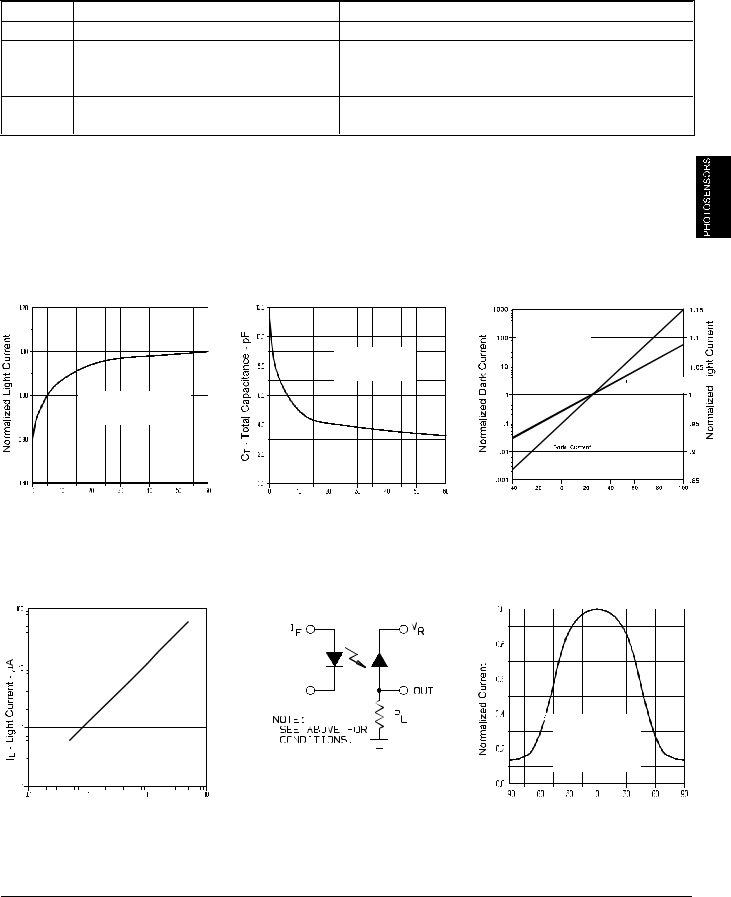
Typical Performance Curves
Normalized Light Current vs |
Total Capacitance vs |
Reverse Voltage |
Reverse Voltage |
TA = 25o C
Ee = 0 mW/cm2 f = 1 MHz
TA = 25o C
λ = 935 nm Normalized to VR = 5 V
VR - Reverse Voltage - V |
VR - Reverse Voltage - V |
Light Current vs. Irradiance |
Switching Time Test Circuit |
VR = 5 V TA = 25o C
λ = 935 nm
Ee - Irradiance - mW/cm2
Normalized Light and Dark
Current vs Ambient Temperature
VR = 5 V
λ=935 nm
Normalized to TA = 25o C
Light Current
DarkCurrent
TA
Light Current vs. Angular
Displacement
Test Conditions:
λ = 935 nm
VR = 5 V
Distance Lens to
Lens = 1.5 inches
θ- Angular Displacement - Deg.
Optek reserves the right to make changes at any time in order to improve design and to supply the best product possible.
Optek Technology, Inc. |
1215 W. Crosby Road |
Carrollton, Texas 75006 |
Fax |
|
|
|
|
|