Universal transmitter form is a paperless way to submit your transmitter forms. You no longer have to print, sign, and mail the forms. This new process is electronic and easy to use. You can access the universal transmitter form online at www.xnxinc.com. Once you have filled out the form, you can submit it electronically. Your information will be processed quickly and efficiently. Xnx Universal Transmitter Form makes submitting your transmitter forms simple and efficient.
You'll discover information about the type of form you would like to prepare in the table. It will show you the span of time you will require to fill out xnx universal transmitter, what parts you will need to fill in, etc.
Question | Answer |
---|---|
Form Name | Xnx Universal Transmitter |
Form Length | 100 pages |
Fillable? | No |
Fillable fields | 0 |
Avg. time to fill out | 25 min |
Other names | xnx xnx honeywell analytics xnx xnx transmitter manual pdf download video, xnx xnx transmitter wiring diagram, xnx transmitter wiring xnx xnx transmitter manual pdf download, xnx transmitter wiring instructions |
Quick Start Guide
XNX Universal Transmitter
Table of Contents
1 |
Introduction |
5 |
|
2 |
Warnings |
6 |
|
3 |
Mounting and Location of Detectors |
8 |
|
|
3.1 |
Mounting the XNX Universal Transmitter |
8 |
4 |
Wiring the XNX transmitter |
11 |
|
|
4.1 |
General Wiring Considerations |
11 |
|
|
Loading��������������������������������������������������������������������������� |
11 |
|
|
Isolation �������������������������������������������������������������������������� |
12 |
|
|
Circuit Protection����������������������������������������������������������� |
12 |
|
|
Loads ������������������������������������������������������������������������������ |
12 |
|
4.2 |
Distance Considerations for Installation |
12 |
Types of Installations ���������������������������������������������������� 12 Power Source Selection������������������������������������������������ 12 Wire Selection ���������������������������������������������������������������� 12 Single Transmitter Distances ��������������������������������������� 13
4.3 |
POD Connections |
16 |
4.4 |
16 |
Setting
4.5 |
Terminal Block Connections |
19 |
4.6 |
EC Personality Wiring |
20 |
|
4�6�1 XNX Electrochemical (EC) Sensor Installation ��������� |
22 |
|
4�6�2 XNX EC Sensor Remote Mounting Kit ����������������������� |
23 |
4.7 mV Personality Wiring |
24 |
|
|
4�7�1 mV Remote Sensor Mounting������������������������������ |
27 |
4.8 |
IR Personality Wiring |
29 |
4�8�1 Connecting a Searchpoint Optima Plus or Searchline Excel ���������������������������������������������������������������������� 30
Attaching the Searchpoint Optima Plus to the XNX Universal Transmitter���������������������������������������������������� 30
Searchline Excel and Searchpoint Optima Plus Re- mote Installation ������������������������������������������������������������ 30
Searchpoint Optima Plus or Searchline Excel Wiring Recommendations��������������������������������������������������������� 31
4�8�2 Connecting Generic mA Device ��������������������������������� 32
XNX Universal Transmitter Quick Start Guide |
3 |
Table of Contents (cont’d) |
|
|
5 Options |
36 |
|
5.1 |
Local HART® Interface |
36 |
5.2 |
Relays |
36 |
5.3 Modbus |
37 |
|
5.4 |
Foundation Fieldbus |
38 |
6 Powering the XNX for the First Time |
39 |
|
6.1 |
XNX Units Configured for EC, mV, and IR (except Searchline |
|
Excel) |
39 |
|
6.2 |
XNX IR Units Configured for Searchline Excel |
40 |
6.3 |
Configuring the XNX Universal Transmitter |
42 |
7 The XNX Front Panel |
43 |
|
7.1 |
Controls and Navigation |
43 |
7.2 |
The General Status Screen |
43 |
7.3 |
Entering the Menu Structure |
45 |
7.4 |
Displaying Transmitter Information |
46 |
8 Gas Calibration Menu |
46 |
|
8.1 |
Calibration |
47 |
|
8.1.1 Calibration Procedure |
47 |
|
8.1.2 Zero and Span Calibration for XNX EC Sensors |
49 |
|
8.1.3 Zero and Span Calibration of XNX EC Hydrogen Sulfide (H2S) |
|
|
Sensors |
49 |
|
8.1.4 XNX EC Sensor Operational Life |
50 |
|
8.1.5 Zero and Span Calibration for MPD Sensors |
50 |
|
8.1.6 MPD Flammable Sensor |
52 |
|
8.1.7 Cross Calibration procedure for |
52 |
|
8.1.8 Calibrating the 705/705HT |
55 |
|
8.1.9 Calibrating the Sensepoint/Sensepoint HT |
55 |
8.2 |
Functional Gas Testing (Bump Test) |
56 |
9 Sensor Data |
57 |
|
9.1 |
Operating and Storage Conditions for Performance Tested |
|
EC Cartridges |
57 |
|
9.2 |
EC Sensor Performance Data, Factory Mutual Verified |
58 |
9.3 |
EC Sensor Performance Data, DEKRA EXAM Verified |
59 |
9.4 |
Other EC Sensors |
60 |
10 XNX Catalytic Bead and IR Replacement Sensor Cartridges |
62 |
|
11 Warning Messages |
63 |
|
12 Fault Messages |
70 |
|
13 Informational Messages |
82 |
|
14 Control Drawings |
84 |
|
15 Certification Labels |
91 |
|
16 Specifications |
94 |
|
17 EC Declaration of Conformity |
96 |
4 |
XNX Universal Transmitter Quick Start Guide |
1 Introduction
The XNX Quick Start Guide is an abbreviated print reference for the installation, operation, and maintenance of the XNX® Universal Transmitter. Refer to the XNX Universal Transmitter Resource CD (Honeywell part number
Manuals
XNX Technical Manual (1998M0738)
XNX Quick Start Guide
MPD Operating Manual
XNX Safety Manual
XNX Foundation Field bus Technical Manual
Control Drawings
1226E0402 XNX Control Drawing- UL,CSA, XM Approved Model
1226E0454 XNX Control Drawing- UL, INMETRO Approved Models
3000E3159 XNX ECC Cartridge Control Drawing- XNXX***** Series EC Cartridges and Remote Mount Kit.
For other sensor types such as Sensepoint Optima Plus, Searchline Excel, model 705 HT, or Sensepoint sensors, refer to their respective manuals for installation and ordering information.
XNX Universal Transmitter Quick Start Guide |
5 |
2 Warnings
High
•Installation must be in accordance with the recognized standards of the appropriate authority in the country concerned.
•Any work on the interior of the detector must be conducted only by trained personnel.
•Ensure that local regulations and site procedures are followed when carrying out any work. Appropriate standards must be followed to maintain the overall certiication of the detector.
•To reduce the risk of ignition of hazardous atmosphere, disconnect the equipment
from the supply circuit before opening the detector enclosure. Conduit runs must have a seal itting connected within 18 inches (45 cm) of the enclosures. Keep the assembly tightly closed during operation.
•Never open the XNX enclosure under power unless the area is known to be non
•The detector must be earthed/grounded for Intrinsic Safety, electrical safety, and to limit the effects of radio frequency interference. Earth/ground points are provided inside and outside the unit. EMI note for applications using shielded cable: Cable shield terminations must be made at the cable glands with suitable EMI type glands. Avoid terminating cable shields at the Earth ground lug inside the XNX enclosure. In cases where wiring is in pipe, a shielded cable is not required. The external terminal is only a supplemental bonding connection where local authorities permit or require such a connection.
•Take care when handling EC sensor cells as they may contain corrosive solutions.
•Do not tamper with or in any way disassemble the sensor cells.
•Do not expose the transmitter or sensor cells to temperatures outside the recommended range.
•Do not expose the sensor to organic solvents or lammable liquids.
•At the end of their working lives, sensors must be disposed of in an environmentally safe manner. Disposal should be according to local waste management requirements and environmental legislation.
•Alternatively, sensors may be securely packaged, clearly marked for environmental disposal, and returned to Honeywell Analytics.
•Do NOT incinerate electrochemical cells as they may emit toxic fumes.
•Verify all outputs, including display, after installation, after service events, and periodically to ensure the safety and integrity of the system.
•Delays resulting from transmission errors between sensor and transmitter extend response times T90 by more than
•As some test gases are hazardous, exhaust the low housing outlet to a safe area. Do not use the XNX Universal Transmitter in
6 |
XNX Universal Transmitter Quick Start Guide |
Hazardous Locations instaLLation requirements (uL/csa/Fm)
•To reduce the risk of ignition of hazardous atmospheres, conduit runs must have a pour gland installed within 18 inches (457mm) of enclosure.
•All ¾ inch NPT conduit, stopping plugs and adapters must be installed with 5 ¼ threads (minimum) engaged to Maintain Explosion Proof rating.
•The XNX Cover Assembly must be fully seated to enclosure 9 threads (minimum) to maintain Explosion Proof rating.
•Stopping Plugs supplied (Honeywell Part Number
•For units itted with the optional relay module: Relay contact ratings are 250 VAC 5A, 24 VDC 5A Resistive Loads Only.
•Use copper conductors only, 60/75°C. Terminal block screws should be tightened to 4.5 lb/in maximum.
•For models
•
•XNX Universal Transmitters carrying UL/CSA/FM approvals that are conigured
for devices measuring %LEL will not allow adjustments to the full scale value. The range is ixed at 100%.
Hazardous Locations instaLLation requirements (ateX)
•Read and understand Technical Manual 1998M0738 before installation and use.
•Use only Certiied M25 cable glands for installation.
•Shielded armoured cable is required for CE compliance.
•special conditions for safe use
•The following applies to the HART Barrier intrinsically safe circuits: For
installations in which both the Ci and Li of the intrinsically safe apparatus exceeds 1% of the Co and Lo parameters of the associated apparatus (excluding the cable), then 50% of Co and Lo parameters are applicable and
shall not be exceeded, i.e. the Ci of the device plus the C of the cable must be less than or equal to 50% of the Co of the associated apparatus, and the Li of the device plus the L of the cable must be less than or equal to 50% of the Lo of the associated apparatus.
•For circuits connected to the EC barrier in which the capacitance and inductance exceed 1% of the permitted values, then the maximum permitted capacitance is limited to 600nF for group IIC and 1uF for group IIIC.
•The connection to the HART circuit shall be rated a minimum of IP 6X.
XNX Universal Transmitter Quick Start Guide |
7 |
3 Mounting and Location of Detectors
caution
The location of the transmitters and sensors should be made in accordance with any relevant local and national legislation, standards or codes of practice. Always replace detectors with a detector of the same type. The detector should be mounted where the gas is most likely to be present. The following points should be noted when locating gas detectors.
•Consider the possible damage caused by natural events e.g. rain or looding when locating detectors.
•Consider ease of access for functional testing and servicing.
•Consider how escaping gas may behave due to natural or forced air currents.
notes:
The placement of detectors should be determined following the advice of experts having specialist knowledge of gas dispersion, experts having knowledge of the process plant system and equipment involved, safety and engineering personnel. The agreement reached on the location of detectors should be recorded.
CSA certiication does not cover XNX EC cartridges or XNX EC cartridge remote mounting kit,
use of HART®, Modbus, or Foundation Fieldbus used for combustible gas performance. HART®, Modbus, or Foundation Fieldbus may be used only for
data collection or record keeping with regards to combustible gas detection.
FM approved conigurations (see the XNX Universal Transmitter Technical Manual, section 6.3 XNX Certiications by Part Number Series) also limit the
use of HART®, Modbus, or Foundation Fieldbus to use for diagnostics, data collection, or record keeping.
The XNX Universal Transmitter is certiied and designed for installation and use worldwide in hazardous areas.
3.1 Mounting the XNX Universal Transmitter
The XNX Universal Transmitter can be mounted in a number of different methods using the integral mounting tabs.
Using the mounting tabs, the XNX can be attached to:
•Flat wall surface
•Unistrut®
With the optional Pipe Mount kit, the XNX can be mounted to pipe of diameter 2 to 6 in (50 to 150mm).
A ceiling mount bracket kit (1226A0358) is also available.
notes:
Agency certiications require that EC and mV sensors face down. Optima sensors must be mounted horizontally.
8 |
XNX Universal Transmitter Quick Start Guide |
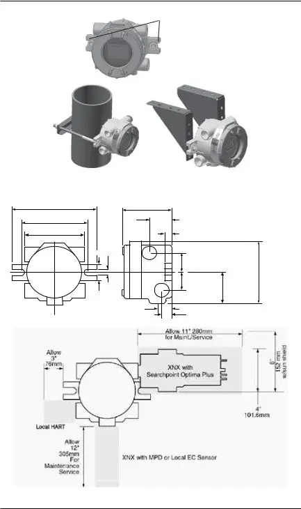
Integral Mounting Lugs
Figure 1. Integral mounting lugs and optional pipe and ceiling mounts
7.75"
196.85 mm
6.00"
15.4mm
5.6"
124.24 mm
4.48" |
|
|
113.8 mm |
2.054" |
|
|
|
|
|
52.18mm |
|
|
0.625" |
|
|
15.88mm |
|
0.55" |
|
|
14.35 mm |
|
|
|
1.768" |
|
|
44.90 mm |
|
|
1.768" |
|
|
44.90 mm |
3.176" |
1.67" |
|
80.67 mm |
|
|
|
42.41 mm |
|
|
1.2" |
|
|
31.75mm |
0.945" |
|
|
24mm |
|
6.138"
158.75mm
Figure 2. XNX Universal Transmitter mounting dimensions and clearances
XNX Universal Transmitter Quick Start Guide |
9 |
Warning
When the XNX is equipped with the optional Remote Mount Kit, the remote sensor MUST be securely
mounted to a ixed position. The Remote Sensor Kit is not intended to be used as a
detector.
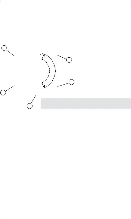
The XNX is conigured with 5 cable/conduit entries built into the housing for wiring and mounting sensors. Figure 3 provides the guidelines to proper installation of the XNX.
A
note
E
While relay wiring can use any available cable/conduit entry in the XNX enclosure, do not use the same cable/ conduit entry for both relay reset and relay signal lines to
D*
avoid electrical noise.
B
C
* Limited access due to IS barrier if equipped with electrochemical cell.
Option |
Position |
|
|
Local HART® Option |
B |
MPD, 705 Series, Sensepoint Series |
C |
|
|
Catalytic Bead Sensor |
C |
|
|
Searchpoint Optima Plus |
A or E |
|
|
Searchline Excel |
Typically C |
|
|
Remote Sensor Connection (except EC ) |
Any remaining |
|
|
Searchpoint Optima Plus - Remote |
Any remaining |
|
|
Modbus® |
Any remaining |
Relays |
Any remaining |
|
|
Foundation Fieldbus |
Any remaining |
|
|
Power |
Any remaining |
|
|
Figure 3. XNX Universal Transmitter cable/conduit entry assignments
10 |
XNX Universal Transmitter Quick Start Guide |
4 Wiring the XNX transmitter
Personality circuit boards determine the XNX behavior based on the sensor type attached to the XNX interface.
The table below deines the three XNX transmitter conigurations and the sensors each support.
XNX IR Personality |
XNX EC Personality |
|
|
|
|
|
|
Searchline Excel |
|
Searchpoint Optima Plus Local/Remote |
XNX EC Sensor |
||
|
|
|
|
|
|
Generic mA Sensors |
|
XNX EC Sensor Remote |
|||
|
Mount Kit |
||||
|
|
|
|
|
|
|
|
|
|
|
|
|
|
|
|
|
|
|
|
|
XNX mV Personality |
|
|
|
|
|
|
|
|
705 Local / Remote |
|
MPD Local (cat bead and IR) |
|
Sensepoint Local / Remote |
|
|
|
|
|
||
705HT Local / Remote |
|
MPD Remote |
Sensepoint PPM Local/Remote |
||
|
|
|
|
|
|
|
|
|
|
|
Sensepoint HT Remote |
|
|
|
|
|
|
caution
Before wiring the transmitter, conirm that the correct personality boards and options are installed.
4.1 General Wiring Considerations
For proper operation of the XNX Universal Transmitter and Sensor Technologies, consideration of wiring induced voltage drops, transient electrical noise and dissimilar Earth ground potentials is imperative in the design and installation of the system.
note:
EMI note for applications using shielded cable: Cable shield must provide 90% coverage of the wiring. Cable shield terminations must be made at the cable glands with suitable
Loading
Wiring for DC Power,
be used.
XNX Universal Transmitter Quick Start Guide |
11 |
Isolation
Isolating power and signal carrying conductors is recommended.
Circuit Protection
Supply circuits must provide over current protection. Class 2 power supplies are required for 24 volt DC supply. Consider Inrush current in specifying any DC supply. Power supply range is 16 to 32 VDC for EC and mV versions, 18 to 32 VDC for Searchpoint Optima Plus and Searchline Excel and 16 to 32 VDC dependent on the limitations of device for the generic
Loads
The use of High Inrush or Inductive loads may affect the performance of the XNX. For best reliability use resistive loads only.
4.2 Distance Considerations for Installation
Types of Installations
There are three basic types of installation: a single transmitter; multiple
transmitters connected to a single power source; and multiple transmitters connected in a
Power Source Selection
XNX Universal Transmitter Maximum Power Consumption
|
|
|
|||
|
|
|
|
|
|
Coniguration |
HART |
HART over |
HART |
HART over |
|
over |
with Relay, Modbus, or |
over |
with Relay, Modbus, or |
||
|
|||||
|
Foundation Fieldbus |
|||
|
(watts) |
(watts) |
(watts) |
(watts) |
|
|
|
|
|
|
|
XNX with toxic |
5.1 |
6.2 |
3.4 |
4.5 |
|
sensors |
|||||
|
|
|
|
||
|
|
|
|
|
|
XNX with catalytic |
5.4 |
6.5 |
3.7 |
4.8 |
|
sensors |
|||||
|
|
|
|
||
|
|
|
|
|
|
XNX with infrared |
5.4 |
6.5 |
3.7 |
4.8 |
|
cartridge |
|||||
|
|
|
|
||
|
|
|
|
|
|
XNX with Search- |
8.6 |
9.7 |
6.9 |
8.0 |
|
point Optima Plus |
|||||
|
|
|
|
||
XNX with |
12.1 |
13.2 |
10.4 |
11.5 |
|
Searchline Excel |
|||||
|
|
|
|
||
|
|
|
|
|
Wire Selection
The type of wire used for connections has an effect on the distance of the installation. This is because some of the voltage is lost in the wire on the way to the transmitter.
12 |
XNX Universal Transmitter Quick Start Guide |
Single Transmitter Distances
For installations that have dedicated wiring between the transmitter and the power supply, use the following chart. These distances assume stranded wire is used.
Single Transmitter Distances
Coniguration |
18 AWG |
16 AWG |
14 AWG |
12 AWG |
[1�0 mm2] |
[1�5 mm2] |
[2�0 mm2] |
[3�5 mm2] |
|
XNX mV or EC |
1140 feet |
1810 feet |
2890 feet |
4620 feet |
With Sensor |
[347 meters] |
[551 meters] |
[880 meters] |
[1408 meters] |
|
|
|
|
|
XNX IR with |
660 feet |
1060 feet |
1690 feet |
2690 feet |
Searchpoint Optima Plus |
[201 meters] |
[323 meters] |
[515 meters] |
[820 meters] |
|
|
|
|
|
XNX IR with |
550 feet |
890 feet |
1410 feet |
2260 feet |
Searchline Excel |
[168 meters] |
[270 meters] |
[430 meters] |
[690 meters] |
|
|
|
|
|
note
If multiple transmitters are using the same power supply, make sure the power supply wattage rating is high enough to power all transmitters simultaneously.
A few selected scenarios are presented here to provide a base to work from.
1.Several transmitters equally spaced from themselves and the power source.
2 Transmitters - Distance “d”
Coniguration |
18 AWG |
16 AWG |
14 AWG |
12 AWG |
[1�0 mm2] |
[1�5 mm2] |
[2�0 mm2] |
[3�5 mm2] |
|
XNX mV or EC |
380 feet |
600 feet |
960 feet |
1540 feet |
With Sensor |
[115 meters] |
[183 meters] |
[292 meters] |
[469 meters] |
|
|
|
|
|
XNX IR with |
220 feet |
350 feet |
560 feet |
900 feet |
Searchpoint Optima Plus |
[67 meters] |
[106 meters] |
[170 meters] |
[274 meters] |
|
|
|
|
|
XNX IR with |
185 feet |
295 feet |
470 feet |
750 feet |
Searchline Excel |
[56 meters] |
[90 meters] |
[143 meters] |
[229 meters] |
|
|
|
|
|
XNX Universal Transmitter Quick Start Guide |
13 |
3 Transmitters - Distance “d”
Coniguration |
18 AWG |
16 AWG |
|
14 AWG |
|
12 AWG |
[1�0 mm2] |
[1�5 mm2] |
|
[2�0 mm2] |
|
[3�5 mm2] |
|
XNX mV or EC |
190 feet |
300 feet |
|
480 feet |
|
770 feet |
With Sensor |
[58 meters] |
[91 meters] |
|
[146 meters] |
|
[234 meters] |
|
|
|
|
|
|
|
XNX IR with |
110 feet |
175 feet |
|
280 feet |
|
450 feet |
Searchpoint Optima Plus |
[33 meters] |
[53 meters] |
|
[85 meters] |
|
[137 meters] |
|
|
|
|
|
|
|
XNX IR with |
90 feet |
145 feet |
|
235 feet |
|
375 feet |
Searchline Excel |
[27 meters] |
[44 meters] |
|
[71 meters] |
|
[114 meters] |
|
|
|
|
|
|
|
|
|
|
|
|
|
|
|
4 Transmitters - Distance “d” |
|
|
|||
|
|
|
|
|
|
|
Coniguration |
18 AWG |
16 AWG |
|
14 AWG |
|
12 AWG |
[1�0 mm2] |
[1�5 mm2] |
|
[2�0 mm2] |
|
[3�5 mm2] |
|
XNX mV or EC |
110 feet |
180 feet |
|
290 feet |
|
460 feet |
With Sensor |
[33 meters] |
[55 meters] |
|
[88 meters] |
|
[140 meters] |
|
|
|
|
|
|
|
XNX IR with |
65 feet |
105 feet |
|
165 feet |
|
270 feet |
Searchpoint Optima Plus |
[20 meters] |
[32 meters] |
|
[50 meters] |
|
[82 meters] |
|
|
|
|
|
|
|
XNX IR with |
55 feet |
85 feet |
|
140 feet |
|
225 feet |
Searchline Excel |
[17 meters] |
[26 meters] |
|
[43 meters] |
|
[68 meters] |
|
|
|
|
|
|
|
|
|
|
|
|
|
|
|
5 Transmitters - Distance “d” |
|
|
|||
|
|
|
|
|
|
|
Coniguration |
18 AWG |
16 AWG |
|
14 AWG |
|
12 AWG |
[1�0 mm2] |
[1�5 mm2] |
|
[2�0 mm2] |
|
[3�5 mm2] |
|
XNX mV or EC |
75 feet |
120 feet |
|
190 feet |
|
300 feet |
With Sensor |
[23 meters] |
[36 meters] |
|
[58 meters] |
|
[91 meters] |
|
|
|
|
|
|
|
XNX IR with |
45 feet |
70 feet |
|
110 feet |
|
180 feet |
Searchpoint Optima Plus |
[13 meters] |
[21 meters] |
|
[33 meters] |
|
[55 meters] |
|
|
|
|
|
|
|
XNX IR with |
35 feet |
55 feet |
|
90 feet |
|
150 feet |
Searchline Excel |
[11 meters] |
[17 meters] |
|
[27 meters] |
|
[46 meters] |
|
|
|
|
|
|
|
14 |
XNX Universal Transmitter Quick Start Guide |
2.Several transmitters installed in pairs with each pair equally spaced from themselves and the power source. These distances assume the paired transmitters are installed within 10 feet [3 meters] of each other.
2 Transmitters - Distance “d”
|
Coniguration |
18 AWG |
16 AWG |
14 AWG |
12 AWG |
|||||||
|
[1�0 mm2] |
[1�5 mm2] |
[2�0 mm2] |
[3�5 mm2] |
||||||||
|
XNX mV or EC |
485 feet |
775 feet |
1230 feet |
1970 feet |
|||||||
|
With Sensor |
[147 meters] |
[235 meters] |
[292 meters] |
[600 meters] |
|||||||
|
|
|
|
|
|
|
|
|
|
|
|
|
|
XNX IR with |
380 feet |
600 feet |
960 feet |
1540 feet |
|||||||
|
Searchpoint Optima Plus |
[115 meters] |
[180 meters] |
[290 meters] |
[470 meters] |
|||||||
|
|
|
|
|
|
|
|
|
|
|
|
|
|
XNX IR with |
280 feet |
440 feet |
700 feet |
1130 feet |
|||||||
|
Searchline Excel |
[85 meters] |
[134 meters] |
[213 meters] |
[344 meters] |
|||||||
|
|
|
|
|
|
|
|
|
|
|
|
|
|
|
|
|
|
|
|
|
|
|
|
||
|
|
|
4 Transmitters - Distance “d” |
|
|
|||||||
|
|
|
|
|
|
|
|
|
|
|
|
|
|
Coniguration |
|
18 AWG |
|
16 AWG |
|
14 AWG |
12 AWG |
|
|||
|
|
[1�0 mm2] |
|
[1�5 mm2] |
|
[2�0 mm2] |
[3�5 mm2] |
|
||||
|
XNX mV or EC |
|
190 feet |
|
300 feet |
|
480 feet |
770 feet |
|
|||
|
With Sensor |
|
[58 meters] |
|
[91 meters] |
|
[146 meters] |
[234 meters] |
|
|||
|
|
|
|
|
|
|
|
|
|
|
|
|
|
XNX IR with |
|
110 feet |
|
175 feet |
|
280 feet |
450 feet |
|
|||
|
Searchpoint Optima Plus |
|
[33 meters] |
|
[53 meters] |
|
[85 meters] |
[137 meters] |
|
|||
|
|
|
|
|
|
|
|
|
|
|
|
|
|
XNX IR with |
|
90 feet |
|
145 feet |
|
235 feet |
375 feet |
|
|||
|
Searchline Excel |
|
[27 meters] |
|
[44 meters] |
|
[71 meters] |
[114 meters] |
|
|||
|
|
|
|
|
|
|
|
|
|
|
||
|
|
|
|
|
|
|
|
|
||||
|
|
|
6 Transmitters - Distance “d” |
|
|
|||||||
|
|
|
|
|
|
|
|
|
|
|
||
|
Coniguration |
|
18 AWG |
|
16 AWG |
|
14 AWG |
|
12 AWG |
|
||
|
|
[1�0 mm2] |
|
[1�5 mm2] |
|
[2�0 mm2] |
|
[3�5 mm2] |
|
|||
|
XNX mV or EC |
|
95 feet |
|
150 feet |
|
240 feet |
|
385 feet |
|
||
|
With Sensor |
|
[33 meters] |
|
[45 meters] |
|
[73 meters] |
|
[117 meters] |
|
||
|
|
|
|
|
|
|
|
|
|
|
||
|
XNX IR with |
|
55 feet |
|
85 feet |
|
140 feet |
|
225 feet |
|
||
|
Searchpoint Optima Plus |
|
[17 meters] |
|
[26 meters] |
|
[42 meters] |
|
[68 meters] |
|
||
|
|
|
|
|
|
|
|
|
|
|
||
|
XNX IR with |
|
45 feet |
|
|
70 feet |
|
|
115 feet |
|
185 feet |
|
|
Searchline Excel |
|
[14 meters] |
|
[21 meters] |
|
[35 meters] |
|
[56 meters] |
|
||
|
|
|
|
|
|
|
|
|
|
|
|
|
XNX Universal Transmitter Quick Start Guide |
15 |
4.3 POD Connections
The illustration in Figure 4 details the connections available on each of the terminal blocks for each type of personality board.
E
F
Option |
Boards |
|
J1 - Remote HART® Connector Only |
|
Personality Boards |
A |
|
B |
|
|
|
C |
personality board terminal |
|
Figure 4. XNX |
|
|
|
block legend |
|
D |
|
Table A
Board Type |
Function |
|
S1 |
|
S2 |
|
EC Personality |
|
Source |
|
|
|
|
mV Personality |
Sink |
|
|
|
||
Output |
|
|||||
|
|
|
|
|
||
IR Personality |
Isolated |
|
|
|
||
|
|
|||||
|
|
|
|
|
|
|
|
|
|
|
|
|
|
|
Table C |
|
|
|
|
|
Board Type |
Function |
|
S3 |
|
S4 |
|
|
|
|
|
|
|
|
IR Personality |
IR |
Source |
|
|
|
|
|
|
|
|
|||
Input |
Sink |
|
|
|
||
|
|
|||||
|
|
|
||||
|
|
|
|
|
|
|
|
|
|
|
|
|
|
|
Table E |
|
|
|
|
|
Board Type |
Connection |
Function |
|
|||
Relay |
TB4 |
Remote Reset |
||||
Connector |
|
|||||
|
|
|
||||
Modbus® |
SW5 |
Bus Loop |
|
|||
|
|
Terminators |
|
|||
Foundation |
SW5 |
Simulation Mode |
||||
Fieldbus |
||||||
|
|
|
|
|
Table B
Board Type |
Connection |
Function |
|
EC Personality |
|
Power, |
|
|
|
|
|
mV Personality |
|
Power, |
|
TB1 |
Sensor |
||
|
|||
|
|
||
|
|
Power, |
|
IR Personality |
|
IR Power and |
|
|
|
Signal |
|
|
|
|
|
|
Table D |
|
|
Board Type |
Connection |
Function |
|
|
|
|
|
EC Personality |
J2 |
EC IS Barrier |
|
|
|
|
|
IR Personality |
TB2 |
Com A and B |
|
|
|
|
|
|
|
|
|
|
Table F |
|
|
Board Type |
Connection |
Function |
|
Relay |
TB3 |
Relay Output |
|
|
|
|
|
Modbus® |
TB3 |
Data Connection |
|
|
|
|
|
Foundation |
TB3 |
Data Connection |
|
Fieldbus |
|||
|
|
4.4
Setting
The XNX Universal Transmitter allows the user to conigure the
POD. The table below shows the S1 and S2 setting and corresponding output coniguration.
|
Output Coniguration |
S1 |
S2 |
|
|
Source |
Down |
Up |
|
|
|
|
|
|
|
Sink |
Up |
Down |
|
|
Isolated |
Down |
Down |
|
|
|
|
|
|
16 |
XNX Universal Transmitter Quick Start Guide |
Power and
16 volts. Failure to perform “Calibrate mA Output” or with loads outside the recommended values may result in diagnostic warning or fault messages.
The total load resistance recommended for the
Controller |
|
|
XNX |
+VE |
1 |
+V |
|
|
|
||
RL |
|
|
|
Signal |
2 |
+mA |
|
|
|
Current |
|
|
|
Flow |
|
3 |
|||
|
|
Figure 5. Sink wiring for XNX
Terminate cable screen at the detector or controller, not both.
Controller |
|
|
XNX |
+VE |
1 |
|
+V |
|
|||
Signal |
2 |
||
RL |
|
Current |
|
|
Flow |
|
|
3 |
|||
|
|
XNX Source Configuration
Figure 6. Source wiring for XNX
Controller |
|
XNX |
+V1 |
+V |
|
|
|
|
+V2 |
+mA |
|
|
|
XNX Isolated Configuration
Figure 7. Isolated wiring for XNX
XNX Universal Transmitter Quick Start Guide |
17 |
The XNX Universal Transmitter power consumption is dependent on the sensor and options for the speciic coniguration. For proper operation, the input
voltage must be maintained at 16 to 32 volts DC (for EC and mV transmitters) or 18 to 32 volts DC (for IR transmitters).
The table below deines the XNX typical and maximum power consumption based on coniguration:
Coniguration |
Max Power |
Inrush |
XNX EC |
6.2 w |
<1A, <10ms@24VDC |
|
|
|
XNX mV |
6.5 w |
<750mA <2ms@24VDC |
|
|
|
XNX IR (Optima) |
9.7 w |
<1A <10ms@24VDC |
|
|
|
XNX IR (Excel) |
13.2 w |
<1A <10ms@24VDC |
|
|
|
HART® devices can operate in one of two conigurations:
HART® Communications
In
the control system. Additionally, concentration, status, diagnostics, and coniguration are available digitally using the HART® protocol.
note:
Use a
The minimum conductor size is 0.51mm diameter (#24 AWG) for cable runs less than 1,524m (5,000 ft) and 0.81mm diameter (#20 AWG) for longer runs.
Cable Length
Most installations are within the 3,000m (10,000 ft) theoretical limit for HART® communication. However, the electrical characteristics of the cable (mostly capacitance) and the combination of connected devices can affect the maximum allowable cable length of a HART® network. The following table shows the effect of cable capacitance and the number of network devices on cable length. The table is based on typical installations of HART® devices in
18 |
XNX Universal Transmitter Quick Start Guide |
Allowable Cable Lengths for Various Capacitances
(for 1 mm, #18 AWG shielded twisted pair)
|
|
Cable Capacitance |
|
Number of |
||
|
|
|
|
|
|
|
|
20 pf/ft |
30 pf/ft |
50 pf/ft |
|
70 pf/ft |
|
|
|
Network |
||||
|
(65 |
(95 |
(160 |
|
(225 |
|
|
|
Devices |
||||
|
pf/m) |
pf/m) |
pf/m) |
|
pf/m) |
|
|
|
|
||||
|
|
|
|
|
|
|
|
9,000 ft |
6,500 ft |
4,200 ft |
|
3,200 ft |
1 |
|
(2,769 m) |
(2,000 m) |
(1,292 m) |
|
(985 m) |
|
|
|
|
||||
|
|
|
|
|
|
|
|
8,000 ft |
5,900 ft |
3,700 ft |
|
2,900 ft |
5 |
Allowable |
(2,462 m) |
(1,815 m) |
(1,138 m) |
|
(892 m) |
|
|
|
|||||
Lengths |
7,000 ft |
5,200 ft |
3,300 ft |
|
2,500 ft |
10 |
|
(2,154 m) |
(1,600 m) |
(1,015 m) |
|
769 m) |
|
|
|
|
||||
|
|
|
|
|
|
|
|
6,000 ft |
4,600 ft |
2,900 ft |
|
2,300 ft |
15 |
|
(1,846 m) |
(1,415 m) |
(892 m) |
|
(708 m) |
|
|
|
|
||||
|
|
|
|
|
|
|
note:
See Appendix A of the XNX Technical Manual for more information about the Local HART® Handheld.
4.5 Terminal Block Connections
Customer connections to the XNX are made via pluggable terminal blocks
secured to the back of the POD. The terminal blocks are keyed and polarized. A color coded label is afixed to assist in wiring when the block is removed from
the POD.
The terminals are suitable for use with 12 to 28 AWG or 0.8 to 2.5mm wire. Wire insulation must be stripped 5/16 (0.312) inches or 8mm. Tighten each terminal to a maximum of 4.5 in/lbs. Up to four terminal blocks will be supplied; each will be conigured with 2, 6, 9, or 10 positions.
Two terminal block jumpers are provided to provide an electrical connection without connecting to the Personality Board. Install the jumpers between pins 1 and 2 and between pins 3 and 4 to support
For user convenience, a second set of terminals has been provided to eliminate the need for a secondary junction box in
note:
Pins 2 and 4 of terminal block TB1 have no internal connection on the
personality board. When used in conjunction with the terminal block jumpers, pins 2 and 4 can provide additional
power feed for
XNX Universal Transmitter Quick Start Guide |
19 |
Terminal Block Jumper |
black |
OUT |
Figure 8. Pluggable terminal block and terminal block jumper
4.6 EC Personality Wiring
Warning
When the XNX is equipped with the optional Remote Mount Kit, the remote sensor MUST be securely
mounted to a ixed position. The Remote Sensor Kit is not intended to be used as a
detector. |
|
||
|
|
J1 |
|
LOCAL |
HART |
||
20 mA |
|
|
|
Operation |
|
|
|
S1 |
S2 |
|
|
|
Source |
|
|
|
Sink |
S1 S2 |
|
|
Isolated |
||
|
|
||
6.2W |
+V |
||
|
|||
|
|
||
max. |
VDC |
||
|
|||
|
|
|
|
|
+mA |
||
|
|||
|
EC |
EC Barrier J2
J1 - Local HART Connector |
|
1 |
|
|
|
|
|
|
|
|
|
|
2 |
|
|
|
|
|
|
|
|
|
|
3 |
|
|
|
|
|
|
|
|
|
|
4 |
|
|
|
|
|
|
|
|
|
|
5 |
|
|
|
|
|
|
|
|
|
|
6 |
|
|
|
|
|
|
|
|
|
|
|
|
S1 and S2 - Signal Output |
|
|
|
|
|
|
|
||
|
Jumper Switch |
|
|
|
|
|
|
|
|
|
S1 |
S2 |
|
|
|
|
|
|
|
SOURCE |
▼ |
▲ |
|
|
|
|
|
|
|
SINK |
▲ |
▼ |
|
|
|
|
|
|
|
ISOLATED |
▼ |
▼ |
XNX EC |
|
|||||
J2 - EC Barrier Connector |
|
|
|
|
|
TB1 |
|
||
|
|
|
|
|
|
|
|||
|
|
|
|
|
|
|
Position |
EC |
|
|
|
|
|
|
|
|
|
1 |
+24 |
|
|
|
|
|
|
|
|
2 |
|
|
|
|
|
|
|
|
|
3 |
0v |
|
|
|
|
|
|
|
|
4 |
|
Figure 9. XNX EC personality board terminal blocks, jumper switches, and terminal block
assignments
20 |
XNX Universal Transmitter Quick Start Guide |
caution
Be certain to dress the wires properly to ensure cabling does not contact switches
Do not force the POD into the enclosure as it may indicate an interference condition resulting in damage to the wiring, POD or switch settings.
Optional Local HART IS Barrier must
be connected to J1
1
2
3
4
+ 5
- 6
EC IS Barrier must be connected to J2
Local HART IS Barrier (optional)
HART
Adaptor
EC IS Barrier
EC Adaptor
Sensor Cartridge
Sensor Retainer
Sensor Cartridge
Sensor Retainer
Weatherproof Cap |
Local Sensor Mounted to Transmitter
Weatherproof Cap |
FOR FM COMPLIANCE, THE SUPPLIED TAG WITH XNXXSH1FM, XNXXSC1FM, AND XNXSO1FM CARTRDIGES MUST BE ATTACHED TO THE TRANSMITTER OR REMOTE MOUNT KIT WHERE INSTALLED.
Sensor Mounted to
Remote Sensor Kit
Figure 10. EC personality wiring
note:
Refer to control drawing 3000E3159 for installation requirements for EC cells and remote mounting.
XNX Universal Transmitter Quick Start Guide |
21 |
4.6.1 XNX Electrochemical (EC) Sensor Installation
caution
For biased sensors (e.g. Nitrogen Dioxide) remove the sensor stabilizer from the bottom of the sensor prior to installation.
Using Figure 11 as a guide, follow the procedure below:
1.Check that the label on the new sensor is the correct gas type.
2.Unscrew the weatherproof cover, loosen the retainer locking screw with the supplied hex key and unscrew the sensor retainer.
3.Plug in the new sensor taking care to align the sensor pins with the connector.
4.Reit the sensor retainer, tighten the locking screw with the supplied hex key and reit the weatherproof cover.
5.Countdown time of up to 180 seconds (dependent on sensor type) is displayed.
6.Acknowledgement of the gas type will be required before proceeding. For more information on setting gas type, see the XNX Technical Manual Section 2.51 Gas Selection.
7.After the sensor is installed and the gas type is conirmed, the Range, alarm levels and other important settings must be set; see appropriate section in Section 6 - Powering the XNX for the First Time.
8.Once the XNX has been conigured, calibrate the detector following the procedures in Section 8.1 - Calibration.
Transmitter
New Sensor
|
|
3 |
|
|
Sensor Retainer & |
|
|
Locking Screw |
|
2 |
4 |
|
|
|
|
1 |
5 |
|
|
|
|
|
Weatherproof Cap |
|
Figure 11. Installing the |
|
22 |
|
XNX Universal Transmitter Quick Start Guide |
4.6.2 XNX EC Sensor Remote Mounting Kit
The remote sensor mounting kit is used to remotely mount the sensor from the transmitter. To remotely mount the sensor, follow the procedure below.
1.Unscrew the weatherproof cover, loosen the retainer locking screw and unscrew the sensor retainer.
2.Remove the sensor by pulling without twisting.
3.Plug the remote sensor cable connector into the bottom of the transmitter and secure the retainer.
4.Route the cable to the location where the remote sensor is to be mounted.
5.Optional: make a loop of cable at the junction box. This will provide some slack for any future
6.Mount the remote sensor junction box. Allow enough room below it to it the sensor and the weatherproof cover.
7.Plug the sensor into the socket at the bottom of the terminal box.
8.Fit the sensor retainer, tighten the locking screw and it the weatherproof cover.
9.Calibrate the detector following the procedures in Section 8.1 - Calibration.
XNX Universal Transmitter Quick Start Guide |
23 |
Connections
Pin # Color
1Yellow
2Green
3Blue
4White
5Red
6 Black
Sensor Cartridge
Sensor Retainer
Weatherproof Cap
Sensor Mounted to
Remote Sensor Kit
caution
Take care not to cut the cable too short. Once cut, additional lengths of cable cannot be added as this will invalidate the intrinsically safe certification. HA also recommends that a loop of cable is made at the junction box to allow slack for any future
The enclosure of the remotely mounted sensor contains aluminum. Care must be taken to avoid ignition hazards due to impact or friction when installed in the Zone 1 location.
All cable entry devices and blanking elements shall be certified in type of explosion protection flameproof enclosure “Ex e”, suitable for the conditions of use and correctly installed.
Figure 12. Installing remote sensor mounting kit
4.7 mV Personality Wiring
XNX Universal Transmitter with the mV personality Board allows interface to a number of Honeywell Analytics’ Multi Purpose Detector (MPD) and ield proven
705 and Sensepoint devices.
caution
Check to ensure the XNX and mV Sensor has the appropriate approvals for your installation prior to commissioning.
Check the mV Sensor you are installing has compatible threads - 3/4 NPT or M25.
Connections from the mV sensor to the XNX are made via a single pluggable terminal block allowing ease of installation and service. HA recommends an 8” (203mm) service length for wiring be maintained. The wire colors for the connections for each sensor type are shown in the table on the following page. Be sure wires for
24 |
XNX Universal Transmitter Quick Start Guide |
note
The black and red wires f.rom the MPD are not used with the XNX mV Personality Board. Ensure that they are properly isolated from live connections. DO NOT CUT.
caution
Be certain to dress the wires properly to ensure cabling does not contact switches
J1 - Local HART Option Connector |
internal |
||
|
S1 and S2 - 20mA Output |
grounding lugs |
|
|
Jumper Switch |
|
|
|
|
|
J1
LOCAL HART
20mA
Operation
S1 |
S2 |
|
|
Source |
|
|
Sink |
S1 S2 |
|
Isolated |
|
|
|
6.5W |
|
+V |
||
|
|
|||
max. |
VDC |
|
||
|
|
|
||
|
|
|
|
|
|
HART |
+mA |
||
|
||||
|
Sensepoint |
MPD,705 |
Ref |
|
|
|
|
Sense |
|
|
|
|
0v |
mV
|
S1 |
S2 |
|
|
|
|
|
|
|
|
|
|
|
|
|
|
|
|
|
|
|
|
|
|
|
|
|
|
|
|
|
|||
|
|
|
|
|
|
|
|
|
|
|
|
|
|
|
|
|
|
|
|
|
|
|
|
|
|
|
|
|
|
|
|
|||
SOURCE |
▼ |
▲ |
|
|
|
|
|
|
|
|
|
|
|
|
|
|
|
|
|
|
|
|
|
|
|
|
|
|
|
|
|
|||
SINK |
▲ |
▼ |
|
|
|
|
|
|
|
|
|
|
|
|
|
|
|
|
|
|
|
|
|
|
|
|
|
|
|
|
|
|||
ISOLATED |
▼ |
▼ |
|
|
|
|
|
|
|
|
|
|
|
|
|
|
|
|
|
|
|
|
|
|
|
|
|
|
|
|
|
|||
|
|
|
|
|
|
|
|
|
|
|
|
|
|
|
|
|
|
|
|
|
|
|
|
|
|
|
|
|
|
|
|
|
|
|
|
|
|
|
|
|
|
|
|
|
|
|
|
|
|
|
|
|
|
|
|
|
|
|
|
|
|
|
|
|
|
|
|
|
|
|
|
|
|
|
|
|
|
|
|
|
|
|
|
|
|
|
|
|
|
|
|
|
|
|
|
|
|
|
|
|
|
|
|
|
|
|
|
|
|
|
|
|
|
|
|
|
|
|
|
|
|
|
|
|
|
|
|
|
|
|
|
|
|
|
|
|
|
|
|
|
|
|
|
|
|
|
|
|
|
|
|
|
|
|
|
|
|
|
|
|
|
|
|
|
|
|
|
|
|
|
|
|
|
|
|
|
|
|
|
|
|
|
|
|
|
|
|
|
|
|
|
|
|
|
|
|
|
|
|
|
|
|
|
|
|
|
|
|
|
|
|
|
|
|
|
|
|
|
|
|
|
|
|
|
|
|
|
|
|
|
|
|
|
|
|
|
|
|
|
|
|
|
|
|
|
|
|
|
|
|
|
|
|
|
|
|
|
|
|
|
|
|
|
|
|
|
|
|
|
|
|
|
|
|
|
|
|
|
|
|
|
|
|
|
|
|
|
|
|
|
|
|
|
|
|
|
|
|
|
|
|
|
|
|
|
|
|
|
|
|
|
|
|
|
|
|
|
|
|
|
|
|
|
|
|
|
|
|
|
|
|
|
|
|
|
|
|
|
|
|
|
|
|
|
|
|
|
|
|
|
|
|
|
|
|
|
|
|
|
|
|
|
|
|
|
|
|
|
|
|
|
|
|
|
|
|
|
|
|
|
|
|
|
|
|
|
|
|
|
|
|
|
|
|
|
|
|
|
|
|
|
|
|
|
|
|
|
|
|
|
|
|
|
|
|
|
|
|
|
|
|
|
|
|
|
|
|
|
|
|
|
|
|
|
|
|
|
|
|
|
|
|
|
|
|
|
|
|
|
|
|
|
|
|
|
|
|
|
|
|
|
|
|
|
|
|
|
|
|
|
|
|
|
|
|
|
|
|
|
|
|
|
|
|
|
|
|
|
|
|
|
|
|
|
|
|
|
|
|
|
|
|
|
|
|
|
|
|
|
|
|
|
|
|
|
|
|
|
|
|
|
|
|
|
1 |
2 |
3 |
4 |
|
|
|
|
|
|
5 |
6 |
|
|
|
|||
|
|
|
|
|
||||
|
|
|
7 |
|
|
|||
|
|
|
|
8 |
|
|||
|
|
|
|
|
|
9 |
||
|
|
|
|
|
|
|
||
|
|
|
|
|
|
|
|
XNX mV
Figure 13. XNX mV personality board wiring
|
|
|
|
Wire Color from Sensor |
|
|
|
||
|
|
|
|
|
|
|
|
|
|
|
|
mV Catalytic Bead Sensor |
|
mv MPD w/IR Sensor |
|||||
Desc� |
|
|
|
Sensept |
|
|
|
|
|
|
705 |
Sensept |
|
IR 5% |
|
||||
|
|
MPD |
Senspt |
PPM* |
|
|
|
IR Flam |
|
|
|
705HT |
CO2 |
|
CH4 |
||||
|
|
|
HT |
|
|
|
|||
|
|
|
|
|
|
|
|||
|
|
|
|
|
|
|
|
|
|
Pins |
|
See subsections in Section 4.4 for pin identiication |
|||||||
|
|
|
|
|
|
|
|
|
|
7 |
Sense |
|
Brown |
|
Red |
|
|
Brown |
|
|
|
|
|
|
|
|
|
|
|
8 |
0v |
|
White |
|
Green |
|
|
White |
|
|
|
|
|
|
|
|
|
|
|
9 |
Ref |
|
Blue |
|
Blue |
|
|
Blue |
|
|
|
|
|
|
|
|
|
|
|
*Internal earth ground; approximately one inch of the black sheath that contains the Sensepoint PPM’s four wires (red, blue, green, silver) must be split to allow the silver grounding wire to reach the internal grounding lugs.
XNX Universal Transmitter Quick Start Guide |
25 |
Internal Ground Lug
S1 S2
J1 HART
|
1 |
|
2 |
|
3 |
|
4 |
+ |
5 |
- |
6 |
Sense |
7 |
Com |
8 |
Ref |
9 |
Terminal Block 1
Optional Local HART IS Barrier must
be connected to J1
Sense 7
Com 8
Ref 9
Local HART
IS Barrier
(optional)
HART
Adaptor
MPD |
Ground Wire from |
|
Sensepoint PPM |
||
705 |
||
|
||
Sensepoint |
|
Figure 14. mV personality wiring
(Refer to the table on the preceding page for wire colors.)
26 |
XNX Universal Transmitter Quick Start Guide |
4.7.1 mV Remote Sensor Mounting
The millivolt (mV) sensor can be mounted remotely from the XNX transmitter.
The distance between the transmitter and the remote sensor must comply with the table below which identiies the proper wire gauges and distances to ensure
proper operation.
|
Metric Wire |
MPD CB1, 705 |
MPD IC1, IV1 & IF1 |
|
AWG |
Series�Sensepoint |
|||
Gauge |
Sensors |
|||
|
Series Sensors |
|||
|
|
|
||
|
|
|
|
|
24 |
0.25 mm2 |
12m (47 ft.) |
30m (97 ft.) |
|
22 |
|
20m (65 ft.) |
50m (162 ft.) |
|
|
|
|
|
|
20 |
0.5 mm2 |
30m (97 ft.) |
80m (260 ft.) |
|
18 |
|
50m (162 ft.) |
120m (390 ft.)* |
|
|
|
|
|
|
16 |
1.0 mm2 |
80m (260 ft.)* |
200m (650 ft.)* |
*The frequency of zero calibrations may increase due to the changes in wire resistance caused by changing temperatures.
To remotely mount the sensor, follow this procedure:
1.Install a junction box in the desired location. Allow suficient room for installation and calibration of the sensor. (MPD sensors must be installed with the sinter pointing down.)
2.Loosen the retainer locking screw on the transmitter with the supplied hex key.
3.Unscrew the transmitter’s weatherproof cover.
4.Run conduit or cable from one of the transmitter’s available conduit entries to the location of the remote junction box in accordance with local requirements. UL and CSA require a conduit pour itting within 45 cm (18 in.) of each enclosure.
5.Mount the remote sensor junction box. Allow enough room below it to it the sensor and the weatherproof cover.
6.Attach the conduit or cable to the remote junction box. The junction box provides a mounting base for the sensor and contains the associated electronic circuit.
UL/CSA Aluminum Junction Box |
ATEX/IEC Junction Box |
Figure 15. Remote junction boxes
XNX Universal Transmitter Quick Start Guide |
27 |
7.Plug the connector into the back of the mV personality board.
8.Install the mV sensor.
9.Terminate wiring at the mV sensor.
10.At the transmitter, pass the wires through the ferrite bead as shown in Figure 16 and terminate the wiring at the pluggable terminal block as shown in Figure 14.
In remote mount MPD conigurations, the three wires from the sensor that connect to the pluggable terminal block must be routed through the supplied ferrite bead (part no.
lnternal Ground Lug (do not use)
Power |
Ferrite Bead
for Remote
Sensor Wiring
mV or IR Remote Sensor
XNX Universal Transmitter
Figure 16. Ferrite bead wiring
11.Verify
12.Calibrate the sensor.
13.Reinstall the weatherproof cover on the transmitter.
Note: Environmental conditions that compromise the IP66 protection provided by the weather proof cover will extend published response times. Safety
protocols or maintenance procedures that consider these environmental conditions are recommended speciic to the installation.
28 |
XNX Universal Transmitter Quick Start Guide |
note
The black and red wires from the MPD are not used with the XNX mV personality board. Ensure that they are properly isolated from live connections. DO NOT CUT.
caution
The enclosure of the remotely mounted 705 HT sensor contains aluminum. Care must be taken to avoid ignition hazards due to impact or friction when installed in the Zone 1 location.
All cable entry devices and blanking elements of the Junction Box shall be certiied in type of
explosion protection “Ex d” or “Ex e”, suitable for the conditions of use and correctly installed.
14.Attach and wire the sensor into the terminal box.
15.Fit the terminal box lid.
16.Fit the sensor retainer, tighten the locking screw and it the weatherproof cover (if required).
17.Calibrate the detector following the procedure in Section 8.1 - Calibration.
Ensure that wiring is adequately protected from mechanical failure in installation. Speciic shorted or open circuit conditions of wiring to the
MPD **I** sensors may result in full scale concentration readings prior to, or preventing the internal diagnostic routines from identifying the external installation fault.
4.8 IR Personality Wiring
The
Excel
Connections from the Searchpoint Optima Plus or Searchline Excel to the XNX are made via two pluggable terminal blocks allowing ease of installation and service (see Figure 20). HA recommends an 8” (203mm) service length for wiring be maintained.
Be sure wires for
For more information see the Searchpoint Optima Plus Operating Instructions (2104M0508) or the Searchline Excel Technical Manual (2104M0506).
caution
Be certain to dress the wires properly to ensure cabling does not contact switches
Do not force the POD into the enclosure as it may indicate an interference condition resulting in damage to the wiring, POD or switch settings.
XNX Universal Transmitter Quick Start Guide |
29 |
Warning
Setting of S3 and S4 while power is applied or improperly set prior to applying power WILL PERMANENTLY DAMAGE the XNX. Both switches must be set in either Source or Sink prior to applying power.
Do not adjust switch settings while power is applied to the XNX; permanent damage WILL occur.
4.8.1Connecting a Searchpoint Optima Plus or Searchline Excel
Connections from the Searchpoint Optima Plus or Searchline Excel to the XNX are made via two pluggable terminal blocks allowing ease of installation and service (see Figure 18). HA recommends an 8” (203mm) service length for wiring be maintained.
The Searchpoint Optima Plus or Searchline Excel can be supplied in either Sink or Source mode operation and is typically labeled on the white wire exiting the Searchpoint Optima Plus or Searchline Excel. Use the table in Figure 18 to set S3 and S4 to the SAME output type that appears on the wire tag of the IR device.
note:
A second,
For more information see the Searchpoint Optima Plus Operating Instructions (2104M0508) or the Searchline Excel Technical Manual (2104M0506).
Attaching the Searchpoint Optima Plus to the XNX Universal Transmitter
For M25 entries, insert the seal (P/N
of the threads. Thread the Optima body into the XNX until the seal compresses and/or Optima bottoms out. Reverse until the
the front of the weather protection are on the bottom (see Figure 17) then tighten the lock nut to the XNX body.
Figure 17. Optima body orientation
The 3/4” NPT entries do not require the seal and locknut, the form of the threads
provide positive locking and sealing.
note:
When attaching the Searchpoint Optima Plus, be sure to coat the threads with an
30 |
XNX Universal Transmitter Quick Start Guide |
Searchline Excel and Searchpoint Optima Plus Remote Installation
Junction Boxes are available for the Searchline Excel and Searchpoint Optima
Plus to facilitate remote mounting from the XNX Universal Transmitter. Junction boxes are available for installations requiring UL/CSA or ATEX approvals.
Consult the Searchline Excel Technical Handbook (2104M0506) or Searchpoint Optima Plus Operating Instructions (2104M0508) for speciics on remote
installations or contact your Honeywell Analytics representative for more information.
For remote mount installations, the maximum distance between the XNX Universal Transmitter and the Searchpoint Optima Plus unit is 33m (100 ft.), using 18 gauge wire.
Searchpoint Optima Plus or Searchline Excel Wiring Recommendations
When wiring the XNX and the Searchpoint Optima Plus or Searchline Excel for remote applications, the General Recommendations of the
standard must be adhered to with the following additions:
1.When mounting the Searchline Excel or Searchpoint Optima Plus, run wiring connections between each Excel or Optima and the XNX in a dedicated separate conduit.
2.Use 18 AWG twisted shielded cable for the RS485 connection between Excel or Optima and the XNX. Make sure that the shield of the cable is grounded to earth and XNX ground on one end ONLY.
3.Avoid running wiring near main cables or other high voltage equipment.
4.DO NOT APPLY 120 Ohm terminating resistors. These resistors are not required due to low data rates.
5.HA recommends that Excel or Optima and the XNX be wired to building ground. The system should be grounded at one point only.
instaLLation tip:
Always issue a soft reset after connecting the Optima and XNX for the irst time. The
soft reset is performed by accessing the XNX calibration menu.
note:
When the soft reset is initiated for the Optima IR Sensor, the
in a few minutes and the faults will be reset automatically in the Non- Latching Mode. The faults must be reset manually in the Latching Mode.
XNX Universal Transmitter Quick Start Guide |
31 |
32
Pair 1: Unit Ground and IR Sense
(Cable Shield Grounded ONE END ONLY)
Pair 3: IR +ve and IR
Pair 2: RS485+ and RS485- (Cable Shield Grounded ONE END ONLY)
(Cable Shield Grounded ONE END ONLY)
XNX Universal Transmitter
Figure 18. XNX IR remote wiring
|
|
|
J1 |
|
LOCAL |
HART |
|||
20 mA |
|
|
||
Operation |
|
|
||
S1 |
S2 |
|
|
|
|
|
Source |
|
|
|
|
Sink |
S1 S2 |
|
|
|
Isolated |
|
|
13.2W |
|
+V |
||
|
|
|||
|
||||
max. |
VDC |
|
||
|
|
|||
|
HART |
+mA |
||
|
||||
|
Searchpoint |
Searchline |
+ Ir |
|
|
- Ir |
|||
|
Sig |
|||
|
Ir |
|
S3 S4
Source
Sink
+ve
IR Sens
IR
RS485-
Power Supply
Twisted Shielded Pair
18 AWG
IR +ve
Junction Box
RS485+
RS485 Cable Shield
Ground ONE END ONLY
IR Sens (silver)
IR +ve (red)
IR
Searchline Excel
RS485+ (yellow)
RS485- (blue)
Unit Gnd (green) Searchpoint Optima Plus
Quick Start Guide
Single Ground Point
4.8.2 Connecting Generic mA Device
IR personality type provides for a Generic mA input under sensor type coniguration. The XNX transmitter can be used to convert the mA input to be
read over HART® protocol or optional Modbus or Foundation Fieldbus and set optional relays (if equipped). Additional coniguration of gas type and unit ID for
reporting is required (see XNX Technical Manual Section 2.51 Gas Selection). For Generic mA devices, input values below 3mA will generate Fault 155.
Use the following schematics to set S3 and S4 to the same output type that appears on the wire tag of the mA device.
XNX S3 and S4 should be in the UP position
Set mA Device and XNX to the same output type.
XNX |
|
mA Device |
24V 7W Max |
|
+V |
+IR |
||
|
|
|
RL |
|
|
Signal |
+mA |
|
|
|
|
|
|
Current |
|
|
Flow |
|
|
XNX S3 and S4 should be in the DOWN position
Set mA Device and XNX to the same output type.
XNX |
mA Device |
+IR |
+V |
|
|
Signal |
|
|
|
RL |
Current |
Flow |
|
|
Figure 19. Generic mA device sink/source schematics
XNX Universal Transmitter Quick Start Guide |
33 |
|
|
|
J1 |
|
|
LOCAL |
HART |
|
|||
20 mA |
|
|
|
||
Operation |
|
|
|
||
S1 |
S2 |
|
|
|
|
|
|
Source |
|
|
|
|
|
Sink |
S1 S2 |
||
|
|
Isolated |
|||
|
|
|
|
||
13.2W |
|
+V |
|
||
|
|
|
|||
|
|
|
|
||
max. |
VDC |
|
|||
|
|
|
|||
|
HART |
+mA |
|
||
|
|
||||
|
Searchpoint |
Searchline |
+ Ir |
|
|
|
- Ir |
||||
|
Sig |
|
|||
|
Ir |
|
|
J1 - Local HART Connector
S1 and S2 - 20mA Output
Jumper Switch
|
S1 |
S2 |
SOURCE |
▼ |
▲ |
|
|
|
SINK |
▲ |
▼ |
ISOLATED |
▼ |
▼ |
S3 and S4 - IR 20mA Input
Jumper Switch
|
S3 |
S4 |
SOURCE |
▼ |
▼ |
SINK |
▲ |
▲ |
XNX IR
1 |
2 |
|
|
|
|
|
|
|
|
3 |
|
|
|
|
|
|
|
|
|
4 |
|
|
|
|
|
|
|
|
|
5 |
|
|
|
|
|
|
|
|
|
6 |
|
|
|
|
|
|
|
|
|
7 |
|
|
|
|
|
|
|
|
|
8 |
|
|
|
|
|
|
|
|
|
9 |
|
|
|
|
|
|
|
|
|
S3 S4
Source
Sink
XNX IR
|
TB1 |
|
|
|
From Searchpoint Optima |
Desc� |
Plus |
|
Searchline Excel |
124v
2 |
|
|
|
|
|
See Common Connections |
|
3 |
Gnd |
||
Section 2.4 |
|||
|
|
||
4 |
|
||
|
|
520mA +
620mA -
7 |
24v |
Red |
|
|
|
8 |
0v |
Black |
|
|
|
9 |
Sig |
White |
TB2
Terminal |
From Searchpoint Optima |
|
Plus |
||
No� |
||
Searchline Excel |
||
|
||
|
|
|
A |
Blue |
|
|
|
|
B |
Orange |
|
|
|
|
|
|
|
|
XNX |
|
|
|
|
Desc. |
From Searchpoint Optima Plus |
|
Searchline Excel |
||
|
||
|
|
|
Earth |
Green/Yellow |
|
|
|
Figure 20. XNX IR personality board terminal blocks, jumper switches, and wiring guide
34 |
XNX Universal Transmitter Quick Start Guide |
|
1 |
|
2 |
|
3 |
|
4 |
|
5 |
+ |
6 |
+24 |
7 |
Gnd |
8 |
Sig |
9 |
A |
1 |
B |
2 |
Optional Local HART IS Barrier must be connected to J1
red
black
white blue
orange
|
|
Searchpoint |
|
|
Optima Plus |
|
|
green, to |
|
Local HART |
building |
|
|
|
|
IS Barrier |
ground |
|
(optional) |
|
HART |
|
green, to building ground |
Adaptor |
|
|
|
|
Figure 21. IR personality wiring - Searchpoint Optima Plus
|
1 |
|
2 |
|
3 |
|
4 |
|
5 |
+ |
6 |
+24 |
7 |
Gnd |
8 |
Sig |
9 |
A |
1 |
B |
2 |
Optional Local HART IS Barrier must be connected to J1
red black
white blue
orange
Local HART
green, to
IS Barrier
building
(optional)
ART aptor
ground
Searchline Excel
Figure 22. IR personality wiring - Searchline Excel
XNX Universal Transmitter Quick Start Guide |
35 |
5 Options
5.1 Local HART® Interface
Available with any sensor technology or option, this option provides an external access to the HART® interface in the XNX. An IS barrier inside the XNX allows
the user to attach an external
entry of the XNX and is intrinsically safe (IS).
Intrinsically Safe Barrier for HART Interface
HART Handheld Interface
Connector w/Protective Cap
Figure 23. XNX Universal Transmitter with HART® interface IS barrier installed
5.2 Relays
The relay option
is provided to silence alarms. TB4 is provided as a connection to a user installed momentary switch to silence alarms remotely.
Exploring the functionality of the relay option board’s remote reset switch
The remote reset switch (designated
The transmitter can be reset by activating a switch
note:
Relays are not available when the Modbus® or Foundation Fieldbus options are installed.
Wiring for the relays is through an available cable/conduit entry to a pluggable terminal block. See Figure 24 for the terminal block legend.
note:
A second,
36 |
XNX Universal Transmitter Quick Start Guide |
TB4
Remote
Reset SW
Relay Ratings 250VAC 5A 24VDC 5A
NC |
1 |
||
|
C |
Level |
|
|
|||
NO |
|
||
NC |
2 |
||
|
|
Level |
|
C |
|||
NO |
|
||
NC |
Fault |
||
C |
|||
|
|||
NO |
|
Warning: Power externally supplied. Disconnect at source prior to servicing.
9 |
8 |
|
|
|
|
|
|
|
|
7 |
|
|
|
|
|
|
|
|
|
6 |
|
|
|
|
|
|
|
|
|
5 |
|
|
|
|
|
|
|
|
|
4 |
|
|
|
|
|
|
|
|
|
3 |
|
|
|
|
|
|
|
|
|
2 |
|
|
|
|
|
|
|
|
|
1 |
|
|
|
|
|
|
|
|
|
TB3
2 1
TB4
TB3 Relay Connections
Warning: Power externally
supplied, disconnect at source
prior to servicing
Relay Contact Ratings:
250 VAC 5 amps
24 VDC 5 amps
Relay
TB3
1NC
2C
3NO
4NC
|
TB3 |
|
|
5 |
C |
61 NO F+
72 NC F+
83 C F-
94 NO F-
TB45 FS
16 1 FS
2 |
2 |
Figure 24. XNX relay option board and terminal block
5.3 Modbus®
Modbus® connections to the XNX are made through a pluggable terminal block on the Modbus® interface circuit board. A loop termination point (SW5) is included on the Modbus® interface board to provide termination of the Modbus® loop.
S5 EOL Term |
RT =120 |
Terminals
In |
Out |
Modbus |
|
+ |
|
+ |
|
- |
|
- |
|
A |
|
A |
|
B |
|
B |
|
S |
|
S |
|
Use shorting jumper |
|
supplied to maintain |
|
connection during |
|
service |
|
SW5 - Loop Termination
10 |
9 |
|
|
|
|
|
|
|
|
|
8 |
|
|
|
|
|
|
|
|
|
|
7 |
|
|
|
|
|
|
|
|
|
|
6 |
|
|
|
|
|
|
|
|
|
|
5 |
|
|
|
|
|
|
|
|
|
|
4 |
|
|
|
|
|
|
|
|
|
|
3 |
|
|
|
|
|
|
|
|
|
|
2 |
|
|
|
|
|
|
|
|
|
|
1 |
|
|
|
|
|
|
|
|
|
|
TB3 Modbus Connections
Use Jumper to maintain connection during service
Modbus®
TB3
1+
2+
3-
4-
5A
6A
7B
8B
9S
10S
Figure 25. XNX Modbus® option board, terminal block, and jumper switch
XNX Universal Transmitter Quick Start Guide |
37 |
5.4 Foundation Fieldbus
Foundation Fieldbus connections to the XNX transmitter are made through a
pluggable terminal block on the Foundation Fieldbus option board, shown in Figure 26. A simulation switch (SW5) is included on the board to enable/disable
simulation mode. Terminals
S5 |
Sim Mode |
|
In |
|
Out |
FFB |
||
F+ |
|
|
F+ |
|
|
|
||
|
||
FS |
|
|
FS |
|
|
Use shorting jumper |
||
supplied to maintain |
||
connection during |
||
service |
|
1 |
2 |
3 |
4 |
5 |
6 |
|
|
||||
|
|
|
|
SW5 -
Sim switch
Jumper assignments
Foundation Fieldbus
ground cable
to internal ground lug
Internal ground lug
Figure 26. Foundation Fieldbus option board, terminal block, and jumper switch
38 |
XNX Universal Transmitter Quick Start Guide |
6 Powering the XNX for the First Time
6.1XNX Units Configured for EC, mV, and IR (except Searchline Excel)
After mounting and wiring the XNX, the plug in sensor should be itted (if equipped) and the installation visually and electrically tested as below.
Warning
Prior to carrying out any work, ensure local and site procedures are followed. Ensure that the associated control panel is inhibited so as to prevent false alarms. Minimum and maximum controller alarm levels should not be set at less than 10% or greater than 90% of the full scale range of the detector. CSA and FM agency limits are 60% LEL or 0.6mg/m3.
caution
The following procedure should be followed carefully and only performed by suitably trained personnel.
1.Check that the transmitter is wired correctly according to this manual and the associated control equipment manual.
2.If equipped, unscrew the weatherproof cover, loosen the sensor retainer locking screw and unscrew the retainer.
3.Plug in the sensor cartridge taking care to align the sensor pins with the connector holes in the PCB.
caution
For toxic sensors, remove the shorting clip from the bottom of the sensor prior to installation. For O2 sensors, there is no shorting clip provided.
4.Reit the sensor retainer, tighten the locking screw and reit the weatherproof cover.
note:
Before replacing the cover on the transmitter housing, coat the threads with
Also inspect the cover
5.Apply power to the XNX which will in turn provide power to the detector.
6.The detector output will be forced to 3mA (default fault/inhibit).
7.The XNX display will enter a start up routine displaying the initialization screen, then the transmitter loads its operating system, data from the sensor and checks if it is the same type transmitter and sensor software version numbers, gas type, the detection range and span calibration gas level, estimated time to next calibration due, and self test result. The
XNX Universal Transmitter Quick Start Guide |
39 |
green, and yellow) are turned on for 1.5 seconds. The LCD then goes blank and the LEDs turn off.
Figure 27. XNX Initialization and General Status screens
note:
In the inal stages of
descriptions of warnings and faults.
8.Once the General Status screen appears, the transmitter and detector are in normal ‘monitoring’ mode.
note:
Calibration of sensors attached to the XNX is mandatory before the detector can be used for gas monitoring. Refer to Section 6.1 -
Calibration for the proper procedure. For EC and mV personalities, perform Accept New Sensor Type before calibrating the sensor.
6.2 XNX IR Units Configured for Searchline Excel
When powering the XNX itted to the Searchline Excel, the following procedure
must be followed to assure proper installation.
caution
The following procedure should be followed carefully and only performed by suitably trained personnel
1.Check that the transmitter is wired correctly according to this manual and the associated control equipment manual.
2.Apply power to the XNX which will in turn provide power to the detector.
3.The detector output will be forced to 3mA (default fault/inhibit).
4.The XNX display will enter a start up routine as described in Section 6.1.7
Figure 28. XNX Initialization and General Status screens
40 |
XNX Universal Transmitter Quick Start Guide |
note:
In the inal stages of
descriptions of warnings and faults.
5.When the XNX completes
6.Set the Path Length for the application, then align the transmitter and receiver with Align Excel.
7.Once the alignment is complete, a Zero Calibration must be performed on the Excel to complete the commissioning process. (See the Searchline Excel Technical Manual for calibration information P/N 2104M0506).
8.Reset any faults displayed on the XNX display. The XNX and Excel are now ready to monitor.
XNX Remote Calibration for MPD Sensors
In addition to functional gas testing to ensure the system is operating properly, remote calibration for the MPD CB1catalytic combustible sensor and MPD IV1 and MPD IF1 infrared combustible sensors can be performed provided the fol- lowing requirements are met:
Remote sensor is installed in an indoor environment
Internal air velocity does not exceed 0.5 m/s
Weather housing part number
A 1 LPM regulator is used for calibration gas delivery
The remote calibration procedure should be performed in accordance with
Section 6.1 with the exception of the weather guard, part number
1226A0411.
Honeywell Analytics recommends MPD sensor calibration at a maximum interval of 180 days (the XNX default value). This value can be reprogrammed in accord-
ance with site procedures to assure the highest level of safety. Correct opera- tion of each sensor should be conirmed before each use by calibration with a certiied test gas of known concentration. In addition, the pellistors used in lammable gas sensors can suffer from a loss of sensitivity when in the presence of poisons or inhibitors, e.g., silicones, sulides, chlorine, lead, or halogenated
hydrocarbons.
1Special states that inhibit the transmitter from detecting gas are indicated as 2 mA on analog outputs.
XNX Universal Transmitter Quick Start Guide |
41 |
6.3 Configuring the XNX Universal Transmitter
The XNX Universal Transmitter can be conigured via the front panel by using the menus available in the Conigure Menu. For information on accessing and
navigating the menus, see Section 7.1 - Controls and Navigation.
The XNX is shipped with the following settings:
Display Language |
English |
||
|
|
|
|
Date Format |
|
mm/dd/yy |
|
|
|
|
|
Time Format |
|
HH:MM |
|
|
|
|
|
mV Sensor Type (w/mV |
|||
personality) |
|
|
|
|
|
|
|
Alarm Levels |
|
Sensor Cartridge Dependent |
|
|
|
|
|
Alarm: Latching |
|||
Fault: |
|||
|
|
||
|
|
|
|
Display Units |
|
PPM, %VOL or %LEL |
|
|
(dependent on personality and sensor choice) |
||
|
|
||
|
|
|
|
|
|
Inhibit: 2.0 mA |
|
|
Warning: 3.0 mA |
||
|
|
Overrange: 21.0 mA |
|
|
|
|
|
Calibration Interval |
180 Days (HA recommends 30 day interval) |
||
|
|
|
|
Unit ID |
|
XNX #nnnnnnnn |
|
|
|
|
|
Relay Settings |
|
Alarm Normally |
|
|
|
|
|
|
HART® |
Address: 0 |
|
Fieldbus |
Mode: |
||
|
|||
Settings |
Modbus® |
Address: 5 |
|
|
(if installed) |
Baud Rate: 19200 |
|
|
|
|
|
Level 1 Password Access |
0000 |
||
|
|
|
|
Level 2 Password Access |
0000 |
||
|
|
|
|
Easy Reset Enabled |
Yes |
||
|
|
|
42 |
XNX Universal Transmitter Quick Start Guide |
7 The XNX Front Panel
The XNX uses magnetic switches to enable non intrusive operation. To activate a magnetic switch, hold the
Figure 29. The XNX front panel display
7.1 Controls and Navigation
Control |
Action |
✓The Enter/Accept key is used to access menus, accept changes
Enter / Accept |
and to respond “YES” to system prompts. |
|
✖The Escape key is used to return to previous menus or to
Escape / Back |
answer “NO” to system prompts. |
|
|
|
|
|
The Left / Decrement arrow is used to move through menu |
Move Left / Decrement Value |
options or decrement values when entering text or numbers. |
|
|
|
The Right / Increment arrow is used to move through menu |
Move Right / Increment Value |
options or Increment values when entering text or numbers. |
7.2 The General Status Screen
Figure 30. General Status screen
The General Status Screen provides a visual indication of the status of the XNX. Warnings, faults, alarm levels and current concentration levels are displayed continuously.
XNX Universal Transmitter Quick Start Guide |
43 |
Current Concentration Level (Numeric)
Status Indicator
Concentration Units
Current Concentration Level
Full Scale
(Bar Graph)Alarm 2 Set Point
Alarm 1 Set Point
Figure 31. General Status screen - normal operating mode
The Normal Operating Mode icon gives visual indication of proper operation. When a warning is triggered, the Warning icon appears and information is displayed on the General Status Screen.
Warning IconWarning Code
Figure 32. General Status Warning - detail
If the fault icon is displayed, a fault condition has been triggered and the display will alternate the display of the target gas concentration and the fault code.
Fault Icon Fault Code
Figure 33. General Status Fault - detail
When an alarm icon is displayed, the target gas concentration exceeds one or both preset alarm levels. The General Status Screen displays the gas concentration and alarm level exceeded.
Alarm Icon |
Alarm Level Triggered |
|
Target Gas
Concentration
Figure 34. General Status Alarm - detail
In an overrange condition, the alarm icon will display but the target gas concentration bar graph and alarm setpoints will lash, see illustration below.
Alarm Level Triggered
Full Scale
Concentration
|
Concentration Bar, Alarm Setpoints Flash |
|
|
|
Figure 35. General Status Overrange - detail |
|
|
In addition to the graphic Alarm, Fault and Warning |
Figure 38. Zero Calibration |
||
Passed |
|||
|
|
||
|
|
||
44 |
XNX Universal Transmitter Quick Start Guide |
indicators, the LEDs on the front panel will lash in a pattern based on the condition:
Condition |
|
LED |
|
|
|
|
|
||
Red |
Green |
Yellow |
||
|
||||
|
|
|
|
|
Alarm 1 |
Solid |
|
|
|
Alarm 2 |
Flashing |
|
|
|
Warning |
|
|
Solid |
|
Fault |
|
|
Flashing |
|
Health |
|
Flashing |
|
7.3 Entering the Menu Structure
Swiping the magnet over the magnetic switch ✓ or ✖ gives the user access to the XNX to reset faults and/or alarms, display current settings or make
adjustments to the device.
note:
If the Reset option is set to Lock, users will not have access to reset alarms and faults. For more information on Security Settings for the XNX, see XNX Universal Transmitter Technical Manual.
|
From the General Status menu, if the ✖ |
|
or ‘escape’ magnetic switch is swiped, |
|
the Alarm Reset Screen activates. This |
|
allows any user to silence alarms and |
Figure 36. Alarm Reset screen |
reset faults generated by the XNX. |
|
Using the ✓ switch resets all alarms and faults and returns to the General Status Screen. Choosing ‘X’ will return to the General Status Screen without resetting the alarms and faults.
Using the ✖ switch will return the user to the General Status Menu. If the user selects ✓ from the General Status menu, it will activate the passcode screen.
Figure 37. Passcode screen
There are two levels that control access based upon the security level of the user. The passcodes for both levels are set at “0000” from the factory.
Level 1 Routine Maintenance |
Level 2 Technician and Password Admin |
Warning
The
Once the Passcode Screen is displayed, the irst passcode digit is highlighted.
Use the switches to increment or decrement through the values. Once the correct value is displayed for the irst digit, ✓ accepts the value and moves to
the next digit or ✖ will move to the previous digit of the passcode.
XNX Universal Transmitter Quick Start Guide |
45 |
✓
Figure 39. Entering the passcode
Repeat for each of the remaining digits in the passcode. If the passcode is not entered correctly, the Invalid Passcode screen is displayed and the user is returned to the General Status screen.
7.4 Displaying Transmitter Information
While in the General Status display, swiping the magnet over the magnetic switch will display information about the transmitter. The General Status display will replace the bargraph in the lower portion of the screen with the unit serial number, date and time, as well as the unit part number.
Figure 40. General Status screen with unit information
8 Gas Calibration Menu
The Gas Calibration menu is used for Zero and Span calibration as well as functional gas testing (bump test). The Gas Calibration menu is accessed from the main menu screen.
✓
Figure 41. Gas Calibration menu
Function |
Symbol |
Gas Calibration
Bump Test
Align Excel
Calibrate mA Output
Soft Reset
46 |
XNX Universal Transmitter Quick Start Guide |
8.1 Calibration
Warning
Do not use the XNX Universal Transmitter in
caution
The calibration procedure should only be performed by qualiied personnel.
note:
The default calibration values for the “Calibration Required” diagnostic
vary based on sensor type. This value can be reprogrammed in
accordance with site requirements to ensure the highest level of safety. Correct operation of each sensor/detector should be conirmed using calibration with a certiied test gas of known concentration before
commissioning. See Section 9 - Sensor Data for calibration gas speciications.
8.1.1 Calibration Procedure
note:
Follow the speciic procedure outlined in the Operating Manual for each
sensing device. The Zero Calibration procedure should be performed prior to the Span Calibration procedure.
1.If using compressed gas cylinder, attach the calibration gas low housing onto the bottom of the sensor and apply the gas.
2.Access the calibration mode. The Gas Calibration menu is for both Zero and Span Calibration.
Figure 42. Gas Calibration menu
Zero Calibration
Sensor Reading
at Current Settings
Figure 43. Zero Calibration screen
Figure 44. Zero Calibration in
Progress
Select ✓ then apply the zero gas. As the sensor
detects the gas and the concentration increases, the values displayed will relect the changing
concentration. Selecting ✖ will return to the Gas Calibration menu.
XNX Universal Transmitter Quick Start Guide |
47 |
3. If the Zero Calibration is successful, the XNX Universal Transmitter will display the Zero Passed screen.
Span Calibration
note:
If a Span Calibration is not required, select the ✖ to skip the Span
Calibration and return to the Calibration menu.
4.When the Zero Calibration is complete or it is skipped, the Span Concentration screen appears to indicate the concentration value of the gas used for calibration.
Figure 45. Span Gas Concentration screen
5.Select ✓ to choose the irst digit and use the switches to increment or decrement the values. Select ✓ to accept the new value and move to the next digit. Continue until all 3 digits have been selected.
Sensor Reading |
Calibration Gas |
|
Concentration |
||
at Current Settings |
||
|
Figure 46. Span Calibration screen
6.Select ✓ then apply the target gas. As the sensor detects the gas and the concentration increases, the sensor reading values in the display will change to relect the changing concentration.
7.When the concentration values stabilize, the gas concentration as read by the installed sensor is stable. At this time, the gas readings are taken by the sensor. The Span Calibration process also determines whether the sensor is within the proper range to accurately detect the target gas.
8.When the sensor has completed the calibration and the span algorithms have determined that it is within range, the Span Passed
screen will appear.
If the calibration is not successful, the Span Failed screen will display. Selecting
✓will return to the Span Concentration screen to begin the span calibration again. ✖ will exit Span Calibration and return to the Main Calibrate screen.
Arrow indicates |
Selecting ‘’ returns to |
gas values too low |
the Span Concentration |
|
screen |
Figure 47. Span Calibration Failed screen
Once the Zero and Span calibrations are completed successfully, the XNX will exit the calibration procedure. Before returning to the Gas Calibration menu however, the user will be prompted to exit with inhibit off, exit with inhibit on, or not exit.
48 |
XNX Universal Transmitter Quick Start Guide |
Figure 48. Exiting options
Warning
While XNX is in Inhibit Mode, alarms are silenced. This will prevent an actual gas event from being reported. Inhibit Mode must be reset after testing or maintenance activities.
8.1.2 Zero and Span Calibration for XNX EC Sensors
caution
Before initial calibration, allow the detector to stabilize for 30 minutes after applying power. When in zero and span calibration mode, the current output from the detector is inhibited (default 3mA) to avoid false alarms.
It is recommended for most sticky gases (i.e.: HCl, Cl2) the tubing should be PTFE with short pieces
of rubber tube to make the inal connection due to the inlexibility of PTFE. This minimizes adhesion
of the gas to the tube surface and allows for more accurate measurement.
Recalibration is recommended if the temperature of local environment has varied by more than
EN performance standards require 10 minutes stabilization time for application of zero and span gas for
To calibrate the detector, use an appropriate span gas cylinder, low regulator set to
compressed gas cylinder (20.9%Vol oxygen) should be used to perform the zero calibration if the area where the detector is located contains any residual amount of the target gas. If no residual gas is present then the background air can be used to perform the zero calibration. Contact your HA representative for details of suitable calibration kits.
To calibrate the detector follow the procedure in Section 8.1.1.
note:
The Oxygen sensor does not require a zeroing procedure. Background air (20.9%Vol oxygen) can be used to span the oxygen sensor in place of a compressed air cylinder (20.9%Vol oxygen).
See section 6.3.2 of the XNX Technical Manual for other EC sensors.
8.1.3 Zero and Span Calibration of XNX EC Hydrogen Sulfide (H2S) Sensors
caution
Before initial calibration, allow the detector to stabilize for 30 minutes after applying power. When in zero and span calibration mode, the current output from the detector is inhibited (default 3mA) to avoid false alarms.
Recalibration is recommended if the temperature of local environment has varied by more than
Hydrogen Sulide sensors can be affected by extreme humidity changes. A
XNX Universal Transmitter Quick Start Guide |
49 |
sudden increase in ambient humidity can result in a
When calibrating Hydrogen Sulide cartridges the following should be taken into account while following the procedure in Section 8.1.1:
1.To zero the sensor, use a compressed gas cylinder of 20.9%Vol oxygen (not Nitrogen). Do not use background air.
2.If a span calibration is to be performed, the span calibration gas should be applied to the sensor immediately after the zeroing procedure. Do not allow the sensor to return to ambient air conditions.
8.1.4 XNX EC Sensor Operational Life
Typical life of a toxic gas sensor is dependent on the application, frequency
and amount of gas exposure. Under normal conditions, with a 3 month visual inspection and 6 month
equal to or greater than the lifetime as listed below:
•12 months for Ammonia and Hydrogen Fluoride sensors. (See Ammonia note below.)
•24 months for Chlorine Dioxide, Oxygen, and other toxic sensors.
caution
Oxygen deicient atmospheres (less than 6%V/V) may result in inaccuracy of reading and
performance.
note:
Ammonia electrochemical cells are reliable and suitable for applications where
no background concentration of ammonia exists. Under these conditions the cells are expected to operate for 12 to 24 months.
These ammonia cells are of the consumptive type. Their operating life can be adversely affected by continuous or excessive exposure to ammonia, or by prolonged exposure to high temperatures and moisture.
To ensure continued detection availability, it is recommended that the detectors are regularly bump tested and a relevant cell replacement program be implemented.
8.1.5 Zero and Span Calibration for MPD Sensors
caution
Extended or frequent exposure to elevated concentrations of combustible gases may affect sensor sensitivity. Verify sensor performance by frequent calibration.
caution
Before initial calibration, allow the detector to stabilize for 30 minutes after applying power. When in zero and span calibration mode, the current output from the detector is inhibited (default 3mA) to avoid false alarms.
50 |
XNX Universal Transmitter Quick Start Guide |
This section describes how to calibrate MPD lammable sensors itted to the
XNX. The calibration adjustments are made on the XNX’s display and gassing is performed at the sensor. This may be locally or remotely located.
The following equipment is required:
•Flow Housing (Part No: 1226A0411)
•Test gas
•Regulator
note:
Zero gas and Span gas should be at roughly the same humidity levels to avoid erroneous cell responses.
1.At the MPD, remove the Weatherproof Cap if equipped.
2.Fit the Flow Adaptor onto the MPD.
Figure 49. Flow adaptor
Reverse the cap removal procedure. The following diagram shows the Flow Adaptor accessory itted to the MPD.
Figure 50. MPD with low adaptor
note
The Gas Calibration menu is for both Zero and Span Calibration.
3.Connect the Flow Adaptor (using either gas pipe) to the regulated cylinder containing a known concentration of the target gas at approximately the sensor alarm point (e.g. 50% LEL Methane in air).
Warning
As some test gases may be hazardous, the Flow Housing outlet should exhaust to a safe area.
4.Follow the procedure in Section 8.1 for both Zero and Span calibrations.
XNX Universal Transmitter Quick Start Guide |
51 |
5.Apply the target gas to the sensor. Pass the gas through the Flow Adaptor at a rate of 0.5 l/m ±0.2 l/m.
note:
Sensors should be calibrated at concentrations representative of those to be measured. It is always recommended that the sensor is calibrated with the target gas it is to detect.
caution
Where the user calibrates any sensor using a different gas, responsibility for identifying and recording calibration rests with the user. Refer to the local regulations where appropriate.
6.Ensure that the sensor and the vicinity around it is clear all traces of the calibration gas before continuing. This is to avoid triggering spurious alarms. If calibration fails at any point, discard the cartridge and replace with a new one.
7.Remove the test equipment, reit the weatherproof cap to the sensor (if previously removed for the test) and return the system to normal operation.
8.1.6MPD Flammable Sensor
The pellistors used in the lammable gas sensor can suffer from a loss of sensitivity when in the presence of poisons or inhibitors, e.g., siliconse, sulides,
chlorine, lead, or halogenated hydrocarbons. The pellistors are poison resistant to maximixe the operational llife of the lammable sensor.
8.1.7 Cross Calibration procedure for
caution
Where the user calibrates any sensor using a different gas, responsibility for identifying and recording calibration rests with the user. Refer to the local regulations where appropriate.
When the
note
•The irst table on page 49 lists the gases according to the reaction they produce at a given detector.
•An eight star (8*) gas produces the highest output, while a one star (1*) gas produces the lowest output. (These are not applicable at ppm levels.)
52 |
XNX Universal Transmitter Quick Start Guide |
Gas |
Star |
Gas |
Star |
Gas |
Star |
|
Rating |
Rating |
Rating |
||||
|
|
|
||||
|
|
|
|
|
|
|
Acetone |
4* |
Ethane |
6* |
Nonane |
2* |
|
|
|
|
|
|
|
|
Ammonia |
7* |
Ethanol |
5* |
Octane |
3* |
|
|
|
|
|
|
|
|
Benzene |
3* |
Ethyl acetate |
3* |
Pentane |
4* |
|
|
|
|
|
|
|
|
Butanone |
3* |
Ethylene |
5* |
Propane |
5* |
|
|
|
|
|
|
|
|
Butane |
4* |
Heptane |
3* |
4* |
||
|
|
|
|
|
|
|
Butyl acetate |
1* |
Hexane |
3* |
Styrene |
2* |
|
|
|
|
|
|
|
|
Butyl acrylate |
1* |
Hydrogen |
6* |
Tetra hydrafuran |
4* |
|
|
|
|
|
|
|
|
Cyclohexane |
3* |
Methane |
6* |
Toluene |
3* |
|
|
|
|
|
|
|
|
Cyclohexanone |
1* |
Methanol |
5* |
Triethylamine |
3* |
|
|
|
|
|
|
|
|
Diethyl ether |
4* |
MIBK |
3* |
Xylene |
2* |
|
|
|
|
|
|
|
To cross calibrate the
1.Obtain the star rating for both the test gas and the gas to be detected from the table above.
2.Set the gas selection to the star rating which is the same star rating of the gas being detected.
3.These values may then be used in the following table to obtain the required meter setting when a 50% LEL test gas is applied to the detector.
* Rating of |
|
* Rating of Gas to be Detected |
|
||||||
Calibration |
|
|
|
|
|
|
|
|
|
8* |
7* |
6* |
5* |
4* |
3* |
2* |
1* |
||
Gas |
|||||||||
|
|
|
|
|
|
|
|
|
|
8* |
50 |
62 |
76 |
95 |
- |
|
- |
- |
|
|
|
|
|
|
|
|
|
|
|
7* |
40 |
50 |
61 |
76 |
95 |
- |
|
- |
|
|
|
|
|
|
|
|
|
|
|
6* |
33 |
41 |
50 |
62 |
78 |
95 |
- |
|
|
|
|
|
|
|
|
|
|
|
|
5* |
26 |
33 |
40 |
50 |
63 |
79 |
95 |
- |
|
|
|
|
|
|
|
|
|
|
|
4* |
- |
26 |
32 |
40 |
50 |
63 |
80 |
95 |
|
|
|
|
|
|
|
|
|
|
|
3* |
- |
- |
26 |
32 |
40 |
50 |
64 |
81 |
|
|
|
|
|
|
|
|
|
|
|
2* |
- |
- |
- |
25 |
31 |
39 |
50 |
64 |
|
|
|
|
|
|
|
|
|
|
|
1* |
- |
- |
- |
- |
25 |
31 |
39 |
50 |
|
|
|
|
|
|
|
|
|
|
note
These settings must only be used with a calibration gas concentration of 50% LEL.
4.If a sensor is to be used to detect a gas other than that for which it was calibrated, the required correction factor may be obtained from the following multiplication table. The meter reading should be multiplied by this number in order to obtain the true gas concentration.
XNX Universal Transmitter Quick Start Guide |
53 |
Sensor |
|
|
Sensor used to detect |
|
|
||||
calibrated |
|
|
|
|
|
|
|
|
|
8* |
7* |
6* |
5* |
4* |
3* |
2* |
1* |
||
to detect |
|||||||||
|
|
|
|
|
|
|
|
||
|
|
|
|
|
|
|
|
|
|
8* |
1.00 |
1.24 |
1.52 |
1.89 |
2.37 |
2.98 |
3.78 |
4.83 |
|
|
|
|
|
|
|
|
|
|
|
7* |
0.81 |
1.00 |
1.23 |
1.53 |
1.92 |
2.40 |
3.05 |
3.90 |
|
|
|
|
|
|
|
|
|
|
|
6* |
0.66 |
0.81 |
1.00 |
1.24 |
1.56 |
1.96 |
2.49 |
3.17 |
|
5* |
0.53 |
0.66 |
0.80 |
1.00 |
1.25 |
1.58 |
2.00 |
2.55 |
|
|
|
|
|
|
|
|
|
|
|
4* |
0.42 |
0.52 |
0.64 |
0.80 |
1.00 |
1.26 |
1.60 |
2.03 |
|
|
|
|
|
|
|
|
|
|
|
3* |
0.34 |
0.42 |
0.51 |
0.64 |
0.80 |
1.00 |
1.27 |
1.62 |
|
|
|
|
|
|
|
|
|
|
|
2* |
0.26 |
0.33 |
0.40 |
0.50 |
0.63 |
0.79 |
1.00 |
1.28 |
|
|
|
|
|
|
|
|
|
|
|
1* |
0.21 |
0.26 |
0.32 |
0.39 |
0.49 |
0.62 |
0.78 |
1.00 |
|
|
|
|
|
|
|
|
|
|
note
Since combustible sensors require oxygen for correct operation, a
mixture of gas in air should be used for calibration purposes. Assuming average performance of the sensor, the sensitivity information in Tables 1 to 3 is normally accurate to +20%.
EXAMPLE
If target gas to be detected is Butane and the calibration gas available is Methane (50% LEL):
1.Look up the star rating for each gas in the irst table on page 51: Butane 4* and Methane 6*.
2.Check the meter settings for 50% LEL calibration gas in the second table: 78.
3.The meter should therefore be set to 78% to give an accurate reading for Butane using 50% LEL Methane as a calibration gas.
note
It is important to calibrate the sensor at the approximate alarm levels to allow for
54 |
XNX Universal Transmitter Quick Start Guide |
8.1.8 Calibrating the 705/705HT
For more complete calibration and coniguration information, see the Type 705 Operating Instructions (p/n:00705M5002).
8.1.9 Calibrating the Sensepoint/Sensepoint HT
For more complete calibration and coniguration information, see the Sieger Sensepoint Technical Handbook (p/n:2106M0502).
8.1.10 Calibrating the Searchline Excel and Searchpoint Optima Plus
Complete calibration and coniguration information can be found in the Searchline Excel Technical Handbook (p/n:2104M0506) and the Searchpoint Optima Plus Operating Instructions (p/n:2108M0501). If properly installed
and maintained, the Searchpoint Optima Plus sensor will not require routine
calibration. This is due to the inherent stability of the IR absorption process and the unit’s fully compensated optical coniguration.
XNX Universal Transmitter Quick Start Guide |
55 |
8.2 Functional Gas Testing (Bump Test)
Warning
Honeywell recommends periodic bump tests (every 30 days or in accordance with customer site procedures) to the sensor to insure proper operation and compliance with the Functional Safety rating of the installation.
Warning
Exposure to desensitizing or contaminating substances or concentrations causing operation of any alarm may affect sensor sensitivity. Following such events, it is recommended to verify sensor performance by performing a functional gas test (bump test).
caution
The calibration procedure should be performed only by qualiied personnel. The appropriate precautions with cylinders of lammable and toxic gases.
It is recommended that the detector is tested frequently to ensure the system is operating properly. Keep in mind different sensor types may require more frequent maintenance depending on the environmental conditions and gases present. The weatherproof cover has a spigot for attaching tubing from a gas
cylinder. This may be used for a simple functional (or bump) test of the sensor. However, this method may not be suitable for all gas types and/or applications
due to environmental conditions. It is the responsibility of the user to ensure suitability of this method for each application.
1.When bump gas is applied to the sensor, the bump test screen displays the current reading of the sensor and the peak reading that has occurred during the bump test.
|
Peak Reading |
Current Sensor |
Full Scale |
|
|
Reading |
|
Alarm Levels
Figure 51. Bump Test screen
2.If the difference between reading and applied gas concentration is outside the acceptable limits for the application follow the procedures for zeroing and calibrating the detector (see Section 8.1).
3.If reading is still inaccurate replace the sensor.
56 |
XNX Universal Transmitter Quick Start Guide |
XNX Universal Transmitter Quick Start Guide
57
9 Sensor Data
9.1Operating and Storage Conditions for Performance Tested EC Cartridges
|
|
|
|
|
Operating Air |
|
Storage Conditions* |
|
||
|
Gas |
|
Cartridge P/N |
Operating Pressure |
|
|
|
|
||
|
|
|
|
|
Speed |
(minimum) |
Temperature |
Pressure |
Humidity |
Time** |
|
|
|
|
|
|
|
||||
|
|
|
|
|
|
|
|
|
|
|
O2 |
Oxygen |
|
XNXXSO1SS |
80 kPa ~ 120 kPa |
0 ~ 6 m/sec |
60 sec. |
0 to 20°C, 32 to 68°F |
80 to 120 KPa |
5 to 95% RH |
6 months |
|
|
|||||||||
|
XNXXSO1FM |
|||||||||
|
|
|
|
|
|
|
|
|
|
|
H2S |
Hydrogen Sulfide |
|
XNXXSH1SS |
80 kPa ~ 120 kPa |
0 ~ 6 m/sec |
60 sec. |
0 to 20°C, 32 to 68°F |
70 to 110 KPa |
30 to 70% RH |
6 months |
|
|
|||||||||
|
XNXXSH1FM |
|||||||||
|
|
|
|
|
|
|
|
|
|
|
|
|
|
|
|
|
|
|
|
|
|
H2S (High) |
Hydrogen Sulfide |
|
XNXXSH2SS |
80 kPa ~ 120 kPa |
0 ~ 6 m/sec |
60 sec. |
0 to 20°C, 32 to 68°F |
70 to 110 KPa |
30 to 70% RH |
6 months |
CO |
Carbon Monoxide |
|
XNXXSC1SS |
80 kPa ~ 120 kPa |
0 ~ 6 m/sec |
60 sec. |
0 to 20°C, 32 to 68°F |
70 to 110 KPa |
30 to 70% RH |
6 months |
|
|
|||||||||
|
XNXXSC1FM |
|||||||||
|
|
|
|
|
|
|
|
|
|
|
|
|
|
|
|
|
|
|
|
|
|
*Store in sealed packages |
**Check cartridge certiicates |
|
|
|
|
|
|
58
XNX Universal Transmitter Quick Start Guide
9.2EC Sensor Performance Data, Factory Mutual Veriied
|
|
|
|
Selectable Full |
|
|
|
Lower |
Lower |
|
|
|
|
Response |
|
Operating Temperature |
Operating |
|||
|
|
|
|
|
|
|
|
|
|
|
|
Humidity |
||||||||
|
|
|
|
Scale Range |
|
Range |
Lower |
Explo- |
|
Selectable |
|
Response |
|
|||||||
|
|
|
|
Default |
Detec- |
Zero |
Default |
Time |
|
|
|
|
|
|||||||
|
|
Gas |
Cartridge P/N |
(Display and |
Incre- |
Alarm |
sive |
Cal Gas |
Time |
Accuracy |
|
|
|
|
||||||
|
|
Range |
tion |
Deviation |
Cal Point |
(T90) |
|
|
Min |
Max |
||||||||||
|
|
|
|
ments |
Limit |
Limit |
Range |
(T50) sec |
|
Min |
Max |
|||||||||
|
|
|
|
|
Limit |
|
|
sec |
|
RH |
RH |
|||||||||
|
|
|
|
Scale) |
|
|
|
(% Vol) |
|
|
|
|
|
|
|
|||||
|
|
|
|
|
|
|
|
|
|
|
|
|
|
|
|
|
|
|||
|
|
|
|
|
|
|
|
|
|
|
|
|
|
|
|
|
|
|
|
|
O |
|
Oxygen |
XNXXSO1FM |
n/a |
23.0% Vol |
n/a |
5.0%Vol |
5% Vol |
n/a |
n/a |
20.9 %Vol |
20.9 %Vol |
T20 <10 |
<30 |
55°C / |
15% |
90% |
|||
|
2 |
|
|
|
|
|
|
|
|
|
(fixed) |
|
|
|
|
131°F |
|
|
||
|
|
|
|
|
|
|
|
|
|
|
|
|
|
|
|
|
|
|
|
|
|
|
|
|
|
|
|
|
|
|
|
30 to 70% |
|
|
|
2 ppm or 10% of |
55°C / |
|
|
||
H2S |
Hydrogen Sulfide |
XNXXSH1FM |
10.0 to 50.0 ppm |
15.0 ppm |
0.1 ppm |
5.0 ppm |
1.5 ppm |
n/a |
10 ppm |
<20 |
<30 |
reading, whichever |
15% |
90% |
||||||
of the |
||||||||||||||||||||
131°F |
||||||||||||||||||||
|
|
|
|
|
|
|
|
|
|
|
selected |
|
|
|
is greater |
|
|
|||
|
|
|
|
|
|
|
|
|
|
|
|
|
|
|
|
|
|
|||
|
|
|
|
|
|
|
|
|
|
|
|
|
|
|
|
|
|
|
||
CO |
Carbon Monoxide |
XNXXSC1FM1 |
100 to 1000 ppm |
300 ppm |
100 ppm |
30 ppm |
15 ppm |
na/ |
full scale |
100 ppm |
<15 |
<30 |
See footnote 1 |
55°C / |
15% |
90% |
||||
range |
||||||||||||||||||||
|
|
|
|
|
|
|
|
|
|
|
|
|
|
|
131°F |
|
|
|||
|
|
|
|
|
|
|
|
|
|
|
|
|
|
|
|
|
|
Footnotes:
1.1. XNXXSC1FM accuracy over temperature <±10% of reading 20°C/68°F to 55°C/131°F, <±20% of reading 20°C/68°F to
Notes:
•Performance igures are measured by test units calibrated at 50% of full scale, at ambient conditions of 20°C, 50% RH, with the EC weatherproof cover attached
•IP rating of FM Cartridges is IP63.
•Barometric pressure effects on the O2 sensor: The output from the O2 sensor has pressure effects of <0.1% change of output per % change in pressure. When the barometric pressure changes by ±20% the output from the O2 sensor changes <±0.4%Vol. However, the oxygen sensor shows transient behavior when subjected to a rapid change in ambient pressure due to either weather or altitude. For example, a 10KPa instantaneous positive pressure step change may cause an overscale alarm condition for a period of about 12
seconds.
•Operating the XNX EC sensor at extended temperature ranges for a prolonged time period exceeding 12 hours my cause deterioration in the sensor performance and shorten sensor life. Extended temperature range for XNX EC sensors is
•Response times may increase at lower temperatures.
•Contact Honeywell Analytics for additional data or details.
XNX Universal Transmitter Quick Start Guide
59
9.3EC Sensor Performance Data, DEKRA EXAM Veriied
|
|
|
Selectable Full |
|
|
|
Lower |
|
|
|
Re- |
T90 |
|
Operating Temperature |
Operating |
|||
|
|
|
|
|
|
|
|
|
|
Humidity |
||||||||
|
|
|
Scale Range |
|
Range |
Lower |
|
Selectable |
Default |
sponse |
Response |
|
|
|
||||
|
|
Cartridge |
Default |
Detec- |
Zero |
Accuracy1 |
|
|
|
|
||||||||
|
Gas |
(Display and |
Incre- |
Alarm |
Cal Gas |
Cal |
Time |
T10 Recov- |
|
|
|
Max |
||||||
|
|
P/N |
Range |
ments |
Limit |
tion |
Variation |
Range |
Point |
(T50) |
ery Time |
|
Min |
Max |
Min RH |
|||
|
|
|
|
Limit |
|
|
RH |
|||||||||||
|
|
|
Scale) |
|
|
|
|
|
|
(sec) |
(sec) |
|
|
|
|
|||
|
|
|
|
|
|
|
|
|
|
|
|
|
|
|
||||
|
|
|
|
|
|
|
|
|
|
|
|
|
|
|
|
|
|
|
O2 |
Oxygen |
XNXXSO1SS |
n/a |
25.0 %Vol |
n/a |
5.0%Vol |
3.5 %Vol |
n/a |
20.9 %Vol |
20.9 %Vol |
T20 <10 |
<30 |
55°C /131°F |
15% |
90% |
|||
(fixed) |
||||||||||||||||||
|
|
|
|
|
|
|
|
|
|
|
|
|
|
|
|
|
|
|
H2S |
Hydrogen Sulfide |
XNXXSH1SS |
10.0 to 50.0 ppm |
15.0 ppm |
0.1ppm |
3.0 ppm |
1.0 ppm |
2.0 ppm |
30 to 70% |
10 ppm |
<20 |
<30 |
55°C / 131°F |
15% |
90% |
|||
H2S (High) |
Hydrogen Sulfide |
XNXXSH2SS |
50 to 500 ppm |
100 ppm |
10 ppm |
5 ppm |
1 ppm |
2 ppm |
of the |
50 ppm |
<20 |
<30 |
55°C / 131°F |
15% |
90% |
|||
selected |
||||||||||||||||||
CO |
Carbon |
XNXXSC1SS |
100 to 500 ppm |
300 ppm |
100 ppm |
15 ppm |
5 ppm |
10 ppm |
full scale |
100 ppm |
<15 |
<30 |
55°C / 131°F |
15% |
90% |
|||
Monoxide |
range |
|||||||||||||||||
|
|
|
|
|
|
|
|
|
|
|
|
|
|
|
|
|||
|
|
|
|
|
|
|
|
|
|
|
|
|
|
|
|
|
|
Footnote:
1. Accuracy of reading at default Alarm 1 concentration (typically 10% FS or defined minimum alarm level setting, whichever is greater) when operated at default full scale.
Note:
•Sensor drift between LDL and negative drift fault limits (typcially > negative zero variation) appear as 0 on the display and outputs of the device.
•
•Operating the XNX EC sensor at extended temperature ranges for a prolonged time period exceeding 12 hours may cause deterioration in sensor performance and shorten sensor life. Extended temperature ranges for XNX EC sensor cartridges are
•Barometric pressure effects on the O2 sensor: The output from the O2 sensor has pressure effects of <0.1% change of output per % change in pressure. When the barometric pressure changes by ±20%, the output from the O2 sensor changes <±0.4%Vol. However, the oxygen sensor shows transient behavior when subjected to a rapid change in ambient pressure due to either weather or altitude. For example, a 10KPa instantaneous positive pressure step change may cause an overscale alarm condition for a period of about 12 seconds.
•Response times may increase at lower temperatures.
•Contact Honeywell Analytics for any additional data or details.
60
XNX Universal Transmitter Quick Start Guide
9.4Other EC Sensors
|
|
|
|
|
|
|
|
Selectable Full |
|
|
|
Lower |
|
Selectable |
Default |
Re- |
Re- |
|
Typical |
Operating Tempera- |
Operating |
|||
|
|
|
|
|
|
|
|
Scale Range |
|
Range |
Lower |
|
sponse |
sponse |
|
Accuracy |
ture |
|
Humidity |
|||||
|
|
|
|
|
|
|
Cartridge |
Default |
Detec- |
Zero De- |
Accuracy1 |
|
||||||||||||
|
|
|
|
|
|
Gas |
(Display and |
Incre- |
Alarm |
Cal Gas |
Cal |
Time |
Time |
@ Lowest |
|
|
|
|
|
|||||
|
|
|
|
|
|
|
P/N |
Range |
ments |
Limit |
tion |
viation |
Range |
Point |
(T50) |
(T90) |
|
Alarm |
Min |
|
Max |
Min RH |
Max RH |
|
|
|
|
|
|
|
|
|
|
Limit |
|
|
|
||||||||||||
|
|
|
|
|
|
|
|
Scale) |
|
|
|
|
|
|
sec |
sec |
|
Level |
|
|||||
|
|
|
|
|
|
|
|
|
|
|
|
|
|
|
|
|
|
|
|
|
||||
|
|
|
|
|
|
|
|
|
|
|
|
|
|
|
|
|
|
|
|
|
|
|
|
|
|
|
HCl |
Hydrogen |
XNXXSR1SS |
10.0 to 20.0 ppm |
10.0 ppm |
1.0 ppm |
5.0 ppm |
0.6 ppm |
|
5.0 ppm |
<452, 3 |
<1502, 3 |
40°C/104°F |
15% |
90% |
||||||||
|
|
Chloride |
|
or 20% |
3 ppm |
|||||||||||||||||||
|
|
|
|
|
|
|
|
|
|
|
|
|
|
|
|
|
of applied gas2, 3 |
|
|
|
|
|
||
|
|
|
|
|
|
|
|
|
|
|
|
|
|
|
|
|
|
|
|
|
|
|
|
|
H |
S (Low) |
Hydrogen Sulfide |
XNXXSH3SS |
n/a |
15.0 ppm |
n/a |
3.0 ppm |
1.0 ppm |
|
10 ppm |
<20 |
<40 |
|
55°C / |
15% |
90% |
||||||||
2 |
|
|
|
|
|
|
|
|
|
|
|
|
|
|
|
|
|
|
3 ppm |
|
131°F |
|
|
|
|
|
|
|
|
|
|
|
|
|
|
|
|
|
|
|
|
|
|
|
|
|
|
||
|
|
SO |
|
Sulfur Dioxide |
XNXXSS1SS |
5.0 to 20.0 ppm |
15.0 ppm |
5.0 ppm |
2.0 ppm |
0.6 ppm |
|
5.0 ppm |
<15 |
<30 |
|
55°C / |
15% |
90% |
||||||
|
|
|
|
|
2 |
|
|
|
|
|
|
|
|
|
|
|
|
|
2 ppm |
|
131°F |
|
|
|
|
|
|
|
|
|
|
|
|
|
|
|
|
|
|
|
|
|
|
|
|
|
|||
SO |
|
(High) |
Sulfur Dioxide |
XNXXSS2SS |
20.0 to 50.0 ppm |
50.0 ppm |
10.0 ppm |
5.0 ppm |
1.5 ppm |
|
25 ppm |
<15 |
<30 |
|
55°C / |
15% |
90% |
|||||||
|
|
2 |
|
|
|
|
|
|
|
|
|
|
|
|
|
|
|
|
5 ppm |
|
131°F |
|
|
|
|
|
|
|
|
|
|
|
|
|
|
|
|
|
|
|
|
|
|
|
|
|
|
|
|
|
|
NH3 |
Ammonia |
XNXXSA1SS |
50 to 200 ppm |
200 ppm |
50 ppm |
20 ppm |
6 ppm |
|
100 ppm |
<60 |
<180 |
|
40°C / |
15% |
90% |
|||||||
|
|
|
20 ppm |
|
104°F |
|||||||||||||||||||
|
|
|
|
|
|
|
|
|
|
|
|
|
|
|
|
|
|
|
|
|||||
NH (High) |
Ammonia |
XNXXSA2SS |
200 to 1000 ppm |
1,000 |
50 ppm |
100 ppm |
30 ppm |
30 to 70% |
300 ppm |
<60 |
<180 |
|
40°C / |
15% |
90% |
|||||||||
|
|
3 |
|
|
|
|
|
|
ppm |
|
|
|
|
|
|
|
|
100 ppm |
|
104°F |
|
|
||
|
|
|
|
|
|
|
|
|
|
|
|
|
|
|
|
|
|
|
|
|
|
|
|
|
|
|
|
Cl |
|
|
Chlorine |
XNXXSL2SS |
n/a |
5.00 ppm |
n/a |
0.50 ppm |
0.15 ppm |
of the |
2.0 ppm |
<20 |
<60 |
|
55°C / |
15% |
90% |
||||
|
|
|
|
2 |
|
|
|
|
|
|
|
|
selected |
|
|
|
|
0.50 ppm |
14°F |
|
131°F |
|
|
|
|
|
|
|
|
|
|
|
|
|
|
|
|
|
|
|
|
|
|
|
|
|
|
||
Cl |
|
|
(High) |
Chlorine |
XNXXSL1SS |
5.0 to 20.0 ppm |
5.0 ppm |
5.0 ppm |
1.0 ppm |
0.6 ppm |
full scale |
2.0 ppm |
<20 |
<30 |
|
55°C / |
15% |
90% |
||||||
|
2 |
|
|
|
|
|
|
|
|
|
|
|
|
range |
|
|
|
|
1 ppm |
14°F |
|
131°F |
|
|
|
|
|
|
|
|
|
|
|
|
|
|
|
|
|
|
|
|
|
|
|
|
|
|
|
|
|
ClO2 |
Chlorine Dioxide |
XNXXSX1SS |
n/a |
1.00 ppm |
n/a |
0.10 ppm |
0.03 ppm |
|
0.5 ppm |
<30 |
<120 |
|
55°C / |
15% |
90% |
|||||||
|
|
|
0.1 ppm |
|
131°F |
|||||||||||||||||||
|
|
NO |
Nitrogen |
XNXXSM1SS |
n/a |
100 ppm |
n/a |
10 ppm |
3 ppm |
|
50 ppm |
<15 |
<30 |
|
55°C / |
15% |
90% |
|||||||
|
|
Monoxide |
|
10 ppm |
|
131°F |
||||||||||||||||||
|
|
|
|
|
|
|
|
|
|
|
|
|
|
|
|
|
|
|
|
|
||||
|
|
NO |
|
Nitrogen Dioxide |
XNXXSN1SS |
5.0 to 50.0 ppm |
10.0 ppm |
5.0 ppm |
5.0 ppm |
1.5 ppm |
|
5 ppm |
<15 |
<30 |
|
55°C / |
15% |
90% |
||||||
|
|
|
|
|
2 |
|
|
|
|
|
|
|
|
|
|
|
|
|
5 ppm |
|
131°F |
|
|
|
|
|
|
H |
|
|
Hydrogen |
XNXXSG1SS |
n/a |
1,000 |
n/a |
100 ppm |
30 ppm |
|
500 ppm |
<60 |
<902 |
|
55°C / |
15% |
90% |
||||
|
|
|
|
2 |
|
|
|
|
ppm |
|
|
|
|
|
|
|
|
|
100 ppm |
|
131°F |
|
|
|
H |
|
(High) |
Hydrogen |
XNXXSG2SS |
n/a |
10,000 |
n/a |
1000 |
300 ppm |
|
5000 |
<15 |
<30 |
|
55°C / |
15% |
90% |
|||||||
|
2 |
|
|
|
|
|
|
|
ppm |
|
ppm |
|
|
|
ppm |
|
|
|
1000 ppm |
|
131°F |
|
|
|
|
|
|
HF |
Hydrogen |
XNXXSF1SS |
n/a |
12.0 ppm |
n/a |
1.5 ppm |
0.4 ppm |
|
5.0 ppm |
120 |
<240 |
|
55°C / |
20% |
75% |
||||||
|
|
|
|
|
|
Fluoride |
|
|
|
|
|
|
|
|
|
|
|
|
1.5 ppm |
|
131°F |
|
|
|
|
|
PH |
|
Phosphine |
XNXXSP1SS |
n/a |
1.20 ppm |
n/a |
0.15 ppm |
0.04 ppm |
|
0.5ppm |
<15 |
<30 |
<+/- 0.02 ppm |
|
40°C / |
10% |
90% |
|||||
|
|
|
|
|
3 |
|
|
|
|
|
|
|
|
|
|
|
|
|
0.15 ppm |
|
104°F |
|
|
See notes and footnotes on following page
XNX Universal Transmitter Quick Start Guide
61
Footnotes (see table on previous page):
1.Accuracy of reading at default Alarm 1 concentration (typically 10%FS or defined minimum alarm level setting, whichever greater) when operated at default full scale.
2.System conditioning may be required to achieve stated results. Contact Honeywell Analytics for details.
3.Measured using calibration flow housing at calibration flow rate
Notes (see table on previous page):
•Data taken at ambient conditions of 20°C, 50% RH.
•Data represents typical values of freshly calibrated sensors without optional accessories attached.
•Performance igures are measured by test units calibrated at 50% of full scale.
•Standard temperature range for XNX EC Sensors is
•Extended temperature ranges for the XNX EC Sensors are
•Accuracy between the temperatures of
•Operating the XNX EC Sensors at extended temperature ranges for a prolonged time period exceeding 12 hours may cause deterioration in sensor performance and shorter sensor life.
•Barometric pressure effects on the O2 sensor: The output from the O2 sensor has pressure effects of <0.1% change of output per % change in pressure. When the barometric pressure changes by ±20% the output from the O2 sensor changes <±0.4%Vol. However, the oxygen sensor shows transient behavior when subjected to a rapid change in ambient pressure due to either weather or altitude. For example, a 10KPa instantaneous positive pressure step change may cause an overscale alarm condition for a period of about 12
seconds.
•Recalibration is recommended if the temperature of local environment has varied by more than ±15°C from the temperature of calibration.
•Response times may increase at lower temperatures.
•Contact Honeywell Analytics for any additional data or details.
62
XNX Universal Transmitter Quick Start Guide
10 XNX Catalytic Bead and IR Replacement Sensor Cartridges
|
|
|
Operating |
Operating |
|
|
|
|
|
|
|
|
|
|
|
|
|
|
|
Humidity |
Air |
|
|
|
|
|
|
|
|
|
|
||
Sensor |
|
Cartridge |
Pressure |
Maximum |
|
|
Default |
|
Cal Gas |
|
|
|
|
|||
Target Gas |
Range (% |
Speed |
Selectable Range3 |
Increment |
Cal Gas Range |
Cal Gas Description |
||||||||||
Type1, 2 |
Part No |
Range |
Range |
Range |
P/N |
|||||||||||
|
RH non- |
(m/s) |
|
|
|
|
|
|
|
|||||||
|
|
|
(kPa) |
|
|
|
|
|
|
|
|
|
|
|||
|
|
|
condensing) |
|
|
|
|
|
|
|
|
|
|
|
||
|
|
|
|
|
|
|
|
|
|
|
|
|
|
|
||
|
|
|
|
|
|
|
|
|
|
|
|
|
|
|||
Carbon Dioxide |
80 - 110 |
0 - 95 |
0 - 6 |
5.00 %Vol |
1.00 to 5.00 %Vol |
1.00 %Vol |
5.00 %Vol |
1.50 to 3.5 %Vol |
Contact HA |
2.5 %VOL CO2 |
in Air |
|||||
|
|
|
|
|
|
|
|
|
|
|
|
|
|
|||
Methane |
80 - 110 |
0 - 95 |
0 - 6 |
5.00 %Vol |
1.00 to 5.00 %Vol |
1.00 %Vol |
5.00 %Vol |
1.50 to 3.5 %Vol |
GFV352 |
2.5 %VOL CH4 |
in Air |
|||||
|
|
|
|
|
|
|
|
|
|
|
|
|
|
|
|
|
Flammables |
80 - 110 |
0 - 95 |
0 - 6 |
100 %LEL |
20 to 100 %LEL3 |
10 %LEL |
100 %LEL |
30 to 70 %LEL |
GFV406 |
1 %VOL C |
H |
8 |
in Air |
|||
|
|
|
|
|
|
|
|
|
|
|
|
3 |
|
|
||
Flammables |
1226A0359 |
80 - 120 |
see footnote 4 |
0 - 6 |
100 %LEL |
20 to 100 %LEL3 |
10 %LEL |
100 %LEL |
30 to 70 %LEL |
GFV352 |
50 %LEL CH |
4 |
in Air |
|||
|
|
|
|
|
|
|
|
|
|
|
|
|
|
|
|
|
1Agency approved hydrogen sensors are |
|
|
|
|
|
|
|
|
|
|
|
|
||||
2When ordering replacement MPD sensor cartridges, the replacement cartridge must be the same type as factory conigured. Substituting a different cartridge will void agency certiication. |
|
|
|
|
|
|||||||||||
3On XNX %LEL units carrying UL/CSA/FM certiications, the range is ixed at 100%LEL and is not adjustable. |
|
|
|
|
|
|
|
|
|
|||||||
4Humidity: 0% to 99% RH |
|
|
|
|
|
|
|
|
|
|
|
|
|
XNX Universal Transmitter Quick Start Guide
63
11 Warning Messages
|
|
Ap- |
Latching / |
Frequency of |
Event History |
|
|
Warning |
Description |
plicable |
Action For Resolution |
||||
Diagnostic |
Data |
||||||
|
|
Sensors |
|
||||
|
|
|
|
|
|
||
|
|
|
|
|
|
|
|
W001 |
XNX 24 VDC |
All |
2 seconds |
XNX supply |
Check wire of 24V power supply to XNX as well as power supply operation. |
||
Supply Bad |
voltage x1000 |
||||||
|
|
|
|
|
|||
|
|
|
|
|
|
|
|
|
XNX Tempera- |
|
|
|
XNX tempera- |
Check location for heat sources. Fit with sunshade or other protection. Change |
|
W002 |
All |
2 seconds |
location of XNX. Check temperature in |
||||
ture Error |
ture (Celsius) |
||||||
|
|
|
|
perature is being measured properly. |
|||
|
|
|
|
|
|
||
|
|
|
|
|
|
|
|
W003 |
Simulated Warn- |
All |
Enabled by |
0 |
Performing an alarm/fault reset will clear all simulation. |
||
ing/Fault |
user |
||||||
|
|
|
|
|
|||
|
|
|
|
|
|
|
|
|
|
|
|
XNX polls |
|
|
|
|
|
|
|
sensor every |
|
|
|
|
Sensor Tem- |
|
|
2 seconds, |
Sensor fault |
Check location for heat sources. Fit with sunshade or other protection. Change |
|
|
Optima |
diagnostic |
or warning |
location of XNX. Check temperature in |
|||
|
perature Error |
||||||
|
|
|
frequency |
code (Note 4) |
ture is being measured properly. |
||
|
|
|
|
||||
|
|
|
|
controlled |
|
|
|
|
|
|
|
by sensor |
|
|
|
|
|
|
|
|
|
|
|
|
|
|
|
XNX polls |
|
|
|
W005 |
|
|
|
sensor every |
|
|
|
|
Sensor Tem- |
|
|
2 seconds, |
Sensor fault |
Check location for heat sources. Fit with sunshade or other protection. Change |
|
|
Excel |
diagnostic |
or warning |
location of XNX. Check temperature in |
|||
|
perature Error |
||||||
|
|
|
frequency |
code (Note 4) |
ture is being measured properly. |
||
|
|
|
|
||||
|
|
|
|
controlled |
|
|
|
|
|
|
|
by sensor |
|
|
|
|
|
|
|
|
|
|
|
|
Sensor Tem- |
|
|
|
Sensor |
Check location for heat sources. Fit with sunshade or other protection. Change |
|
|
ECC |
2 seconds |
temperature |
location of XNX. Check temperature in |
|||
|
perature Error |
||||||
|
|
|
|
(Celsius) |
ture is being measured properly. |
||
|
|
|
|
|
|||
|
|
|
|
|
|
|
64
XNX Universal Transmitter Quick Start Guide
|
|
Ap- |
Latching / |
Frequency of |
Event History |
|
|
Warning |
Description |
plicable |
Action For Resolution |
||||
Diagnostic |
Data |
||||||
|
|
Sensors |
|
||||
|
|
|
|
|
|
||
|
|
|
|
|
|
|
|
|
|
ECC, |
|
|
Raw gas |
Check sensor location for external interference. Perform zero calibration. If prob- |
|
|
Negative Drift |
2 seconds |
concentration |
||||
|
mV |
lem persists after zero calibration and no interference exists, replace sensor. |
|||||
|
|
|
|
of sensor |
|||
|
|
|
|
|
|
||
|
|
|
|
|
|
|
|
|
|
|
|
XNX polls |
|
|
|
W006 |
|
|
|
sensor every |
|
|
|
|
|
|
2 seconds, |
Sensor fault |
|
||
|
|
Optima, |
|
Check sensor location for external interference. Perform zero calibration. If prob- |
|||
|
Negative Drift |
diagnostic |
or warning |
||||
|
Excel |
lem persists after zero calibration and no interference exists, replace sensor. |
|||||
|
|
|
frequency |
code |
|||
|
|
|
|
|
|||
|
|
|
|
controlled |
|
|
|
|
|
|
|
by sensor |
|
|
|
|
|
|
|
|
|
|
|
|
|
|
|
|
Number of |
|
|
|
|
|
|
|
days remain- |
|
|
|
|
|
|
|
ing until |
Time since the last span calibration has exceeded a deined limit. Performing a |
|
|
Calibration |
|
|
|
calibration |
||
W007 |
All |
2 seconds |
successful span calibration will clear the condition. The limit is the |
||||
Required |
expires, nega- |
||||||
|
|
|
|
calibration interval. W007 can be disabled by setting the calibration interval to 0. |
|||
|
|
|
|
|
tive = number |
||
|
|
|
|
|
|
||
|
|
|
|
|
of days |
|
|
|
|
|
|
|
expired |
|
|
|
|
|
|
|
|
|
|
|
|
|
|
XNX polls |
|
|
|
|
|
|
|
sensor every |
|
|
|
|
Sensor 24 VDC |
Optima, |
|
2 seconds, |
Sensor fault |
Check wire of 24V power supply to XNX as well as power supply operation. Also |
|
W009 |
diagnostic |
or warning |
|||||
Supply Bad |
Excel |
check wiring between XNX and Optima/Excel. |
|||||
|
|
frequency |
code (Note 4) |
||||
|
|
|
|
|
|||
|
|
|
|
controlled |
|
|
|
|
|
|
|
by sensor |
|
|
|
|
|
|
|
|
|
|
XNX Universal Transmitter Quick Start Guide
65
|
|
Ap- |
Latching / |
Frequency of |
Event History |
|
|
Warning |
Description |
plicable |
Action For Resolution |
||||
Diagnostic |
Data |
||||||
|
|
Sensors |
|
||||
|
|
|
|
|
|
||
|
|
|
|
|
|
|
|
|
|
|
|
XNX polls |
|
|
|
|
|
|
|
sensor every |
|
|
|
|
Sensor Path |
|
|
2 seconds, |
Sensor fault |
|
|
|
Optima |
diagnostic |
or warning |
Check location for external interference. Check sensor for dirty windows. |
|||
|
Obscured |
||||||
|
|
|
frequency |
code (Note 4) |
|
||
|
|
|
|
|
|||
|
|
|
|
controlled |
|
|
|
W010 |
|
|
|
by sensor |
|
|
|
|
|
|
|
|
|
||
|
|
|
XNX polls |
|
|
||
|
|
|
|
|
|
||
|
|
|
|
sensor every |
|
|
|
|
|
|
|
2 seconds, |
Sensor fault |
Check location for external interference or obstructions in the IR path. Check |
|
|
Beam Block |
Excel |
diagnostic |
or warning |
|||
|
sensor for dirty windows. Check Excel alignment. |
||||||
|
|
|
|
frequency |
code (Note 4) |
||
|
|
|
|
|
|||
|
|
|
|
controlled |
|
|
|
|
|
|
|
by sensor |
|
|
|
|
|
|
|
|
|
|
|
|
|
|
|
XNX polls |
|
|
|
|
|
|
|
sensor every |
|
|
|
|
Sensor Internal |
|
|
2 seconds, |
Sensor fault |
|
|
W011 |
Optima |
Latching |
diagnostic |
or warning |
Remove and return to Honeywell for repair. |
||
Lamp Issue |
|||||||
|
|
|
frequency |
code (Note 4) |
|
||
|
|
|
|
|
|||
|
|
|
|
controlled |
|
|
|
|
|
|
|
by sensor |
|
|
|
|
|
|
|
|
|
|
|
|
|
|
|
XNX polls |
|
|
|
|
|
|
|
sensor every |
|
|
|
|
|
Optima, |
|
2 seconds, |
Sensor fault |
Check sensor location for external interference, check sensor for operation and |
|
W012 |
Excessive Float |
diagnostic |
or warning |
||||
Excel |
|||||||
|
|
|
frequency |
code (Note 4) |
|||
|
|
|
|
|
|||
|
|
|
|
controlled |
|
|
|
|
|
|
|
by sensor |
|
|
|
|
|
|
|
|
|
|
66
XNX Universal Transmitter Quick Start Guide
|
|
Ap- |
Latching / |
Frequency of |
Event History |
|
|
Warning |
Description |
plicable |
Action For Resolution |
||||
Diagnostic |
Data |
||||||
|
|
Sensors |
|
||||
|
|
|
|
|
|
||
|
|
|
|
|
|
|
|
|
Sensor Loop |
|
|
XNX polls |
|
|
|
|
Failure, (Sensor |
|
|
|
|
||
|
|
|
sensor every |
|
Check that supply voltage is stable. Check wiring between Optima/Excel and |
||
|
is losing/has |
|
|
|
|||
|
|
|
2 seconds, |
Sensor fault |
XNX. Check loop impedance of wiring. Check that switches S3 and S4 are set |
||
|
lost mA output |
Optima, |
|
||||
W013 |
Latching |
diagnostic |
or warning |
correctly. If the switch settings need to be changed, power down the transmitter |
|||
signal. These |
Excel |
||||||
|
|
frequency |
code (Note 4) |
before changing the switch settings. Once the problem has been resolved, a soft |
|||
|
are detected |
|
|
||||
|
|
|
controlled |
|
reset must be performed for the Calibration menu to clear W013. |
||
|
by Optima and |
|
|
|
|||
|
|
|
by sensor |
|
|
||
|
Excel. |
|
|
|
|
||
|
|
|
|
|
|
||
|
|
|
|
|
|
|
|
|
|
|
|
XNX polls |
|
|
|
|
|
|
|
sensor every |
Sensor fault |
|
|
|
Sensor Real |
|
|
2 seconds, |
Reset “date and time” in Excel, |
||
W014 |
Excel |
or warning |
|||||
Time Clock issue |
diagnostic |
time.” If not retained, remove and return to Honeywell for repair. |
|||||
|
|
|
code (Note 4) |
||||
|
|
|
|
controlled |
|
||
|
|
|
|
|
|
||
|
|
|
|
by sensor |
|
|
|
|
|
|
|
|
|
|
|
|
|
|
|
XNX polls |
|
|
|
|
|
|
|
sensor every |
|
|
|
|
Sensor Internal |
Optima, |
Latching and |
2 seconds, |
Sensor fault |
|
|
|
diagnostic |
or warning |
Remove and return to Honeywell for repair. |
||||
|
Failure |
Excel |
|||||
|
frequency |
code (Note 4) |
|
||||
|
|
|
|
|
|||
|
|
|
|
controlled |
|
|
|
W015 |
|
|
|
by sensor |
|
|
|
|
|
|
|
|
|
||
|
|
|
XNX polls |
|
|
||
|
|
|
|
|
|
||
|
|
|
|
sensor every |
|
|
|
|
Sensor has an |
|
|
2 seconds, |
Sensor fault |
|
|
|
internal software |
Excel |
Latching |
diagnostic |
or warning |
Cycle Excel power and conirm “fault cleared.” If not, replace sensor. |
|
|
error |
|
|
frequency |
code (Note 4) |
|
|
|
|
|
|
controlled |
|
|
|
|
|
|
|
by sensor |
|
|
|
|
|
|
|
|
|
|
XNX Universal Transmitter Quick Start Guide
67
|
|
Ap- |
Latching / |
Frequency of |
Event History |
|
|
Warning |
Description |
plicable |
Action For Resolution |
||||
Diagnostic |
Data |
||||||
|
|
Sensors |
|
||||
|
|
|
|
|
|
||
|
|
|
|
|
|
|
|
|
|
|
|
XNX polls |
|
|
|
|
|
|
|
sensor every |
|
|
|
|
Sensor Instal- |
|
|
2 seconds, |
Sensor fault |
|
|
W016 |
lation Not |
Excel |
diagnostic |
or warning |
Check Excel alignment. Perform a zero calibration. |
||
|
Complete |
|
|
frequency |
code (Note 4) |
|
|
|
|
|
|
controlled |
|
|
|
|
|
|
|
by sensor |
|
|
|
|
|
|
|
|
|
|
|
|
|
|
|
XNX polls |
|
|
|
|
|
|
|
sensor every |
|
|
|
|
General Diag- |
Optima, |
|
2 seconds, |
Sensor fault |
Check sensor connections, check sensor operation, it replacement sensor, |
|
W018 |
diagnostic |
or warning |
|||||
nostics |
Excel |
replace personalty board. |
|||||
|
|
frequency |
code (Note 4) |
||||
|
|
|
|
|
|||
|
|
|
|
controlled |
|
|
|
|
|
|
|
by sensor |
|
|
|
|
|
|
|
|
|
|
|
|
|
|
|
XNX polls |
|
|
|
|
|
|
|
sensor every |
|
|
|
|
Sensor Internal |
|
|
2 seconds, |
Sensor fault |
|
|
W019 |
5V Power Sup- |
Excel |
diagnostic |
or warning |
Remove and return to Honeywell for repair. |
||
|
ply Defect |
|
|
frequency |
code (Note 4) |
|
|
|
|
|
|
controlled |
|
|
|
|
|
|
|
by sensor |
|
|
|
|
|
|
|
|
|
|
|
W020 |
Forced mA |
All |
Latching |
1 second |
Forced mA |
Indicates that a forced mA condition was left on for more than 15 minutes. No |
|
Timeout |
action required as mA operation will be returned to normal automatically. |
||||||
|
|
|
|
|
|||
|
|
|
|
|
|
|
|
|
|
|
|
|
Forced |
|
|
|
Forced Relay |
|
|
|
relay status, |
Indicates that a forced relay condition was left on for more than 15 minutes. No |
|
W021 |
All |
Latching |
1 second |
1=Alarm1 on, |
|||
Timeout |
action required as relay operation will be returned to normal automatically. |
||||||
|
|
|
|
2=Alarm2 on, |
|||
|
|
|
|
|
|
||
|
|
|
|
|
4=Fault on |
|
|
|
|
|
|
|
|
|
68
XNX Universal Transmitter Quick Start Guide
|
|
Ap- |
Latching / |
Frequency of |
Event History |
|
|
Warning |
Description |
plicable |
Action For Resolution |
||||
Diagnostic |
Data |
||||||
|
|
Sensors |
|
||||
|
|
|
|
|
|
||
|
|
|
|
|
|
|
|
|
|
|
|
When user |
1=new sensor, |
Generated after accepting a new mV sensor or changing the mV sensor type or |
|
|
|
|
|
2=changed |
|||
|
mV Sensor Cali- |
|
|
changes |
changing the mV gas selection. This is a warning to user that a span calibration |
||
W022 |
mV |
Latching |
personality, |
||||
bration Needed |
sensor type |
should be performed. If a span calibration is not performed, the default calibra- |
|||||
|
|
|
3=changed |
||||
|
|
|
|
or gas |
tion values will be used. |
||
|
|
|
|
gas |
|||
|
|
|
|
|
|
||
|
|
|
|
|
|
|
|
|
|
|
|
XNX polls |
|
|
|
|
|
|
|
sensor every |
|
|
|
|
Low Optical |
|
|
2 seconds, |
Sensor fault |
Check location for external interference or obstructions in the IR path. Check |
|
W023 |
Excel |
diagnostic |
or warning |
sensor for dirty windows. Check Excel alignment. Check Beam Block Low |
|||
Sample Signal |
|||||||
|
|
|
frequency |
code (Note 4) |
Signal Percentage setting in the transmitter. |
||
|
|
|
|
||||
|
|
|
|
controlled |
|
|
|
|
|
|
|
by sensor |
|
|
|
|
|
|
|
|
|
|
|
|
|
|
|
Dependent |
|
|
|
|
|
|
|
on sensor, |
|
|
|
|
|
|
|
typically |
|
|
|
W024 |
Relex Failure |
ECC |
Latching |
8 hours; |
0 |
ECC sensor is nearing end of life. Replace sensor. |
|
Warning |
Once fault |
||||||
|
|
|
|
|
|||
|
|
|
|
is detected: |
|
|
|
|
|
|
|
every 15 |
|
|
|
|
|
|
|
minutes |
|
|
|
|
|
|
|
|
|
|
|
W025 |
Safety variable |
All |
Latching |
2 seconds |
Note 3 |
Contact Honeyewell Analytics Service Department. |
|
fail warning |
|||||||
|
|
|
|
|
|
||
|
|
|
|
|
|
|
XNX Universal Transmitter Quick Start Guide
69
notes note 3:
Subtypes |
Decimal |
Bit |
Hex |
|
Description |
|
|
|
|
|
|
|
1 |
0 |
1 |
1 |
= CRC error in safety critical RAM block |
|
|
|
|
|
|
|
2 |
1 |
2 |
1 |
= Error reloading safety critical RAM block from EEPROM |
|
|
|
|
|
|
|
4 |
2 |
4 |
1 |
= Error loading data from Personality board |
|
|
|
|
|
|
|
8 |
3 |
8 |
1 |
= Excel signal level has been below the low signal level threshold for at least 24 hours |
|
|
|
|
|
|
|
16 |
4 |
10 |
1 |
= Excel beam blocked |
|
|
|
|
|
|
|
32 |
5 |
20 |
1 |
= Personality board error code > 0 |
|
|
|
|
|
|
|
64 |
6 |
40 |
1 |
= Option board error code > 0 |
Fault 2 Event |
|
|
|
|
|
128 |
7 |
80 |
1 |
= IR mA input > 1 mA and < 3.4 mA |
|
Bits |
|
|
|
|
|
256 |
8 |
100 |
1 |
= IR mA input < 1.0 mA |
|
|
|
|
|
|
|
|
512 |
9 |
200 |
1 |
= IR forced 10 mA not within |
|
|
|
|
|
|
|
1024 |
10 |
400 |
1 |
= gains from PGA don't match local copy |
|
|
|
|
|
|
|
2048 |
11 |
800 |
1 |
= error reading or writing EEPROM |
|
|
|
|
|
|
|
4096 |
12 |
1000 |
1 |
= ECC relex failure |
|
|
|
|
|
|
|
8192 |
13 |
2000 |
1 |
= RAM test failure |
|
|
|
|
|
|
|
16384 |
14 |
4000 |
1 |
= Program memory CRC failure |
|
|
|
|
|
|
|
32768 |
15 |
8000 |
1 |
= Op code test failure |
|
|
|
|
|
|
Fault 3 Event |
1 |
|
|
Interrupt integrity test failure |
|
Bits |
|
|
|||
|
|
|
|
|
|
|
|
|
|
|
|
note 4:
Optima and Excel fault and warning codes are displayed in the Event History data ield.
70
XNX Universal Transmitter Quick Start Guide
12 Fault Messages
|
|
Appli- |
Latching / |
Frequency of |
|
|
|
Fault |
Description |
cable |
Event History Data |
Action For Resolution |
|||
Diagnostic |
|||||||
|
|
Sensors |
ing |
|
|
||
|
|
|
|
|
|||
|
|
|
|
|
|
|
|
|
|
|
|
ECC & mV: |
Note 2. Optima or Excel: |
If repeated, check supply voltage, check |
|
|
Unexpected Sen- |
|
|
main loop x2; |
|||
F101 |
All |
Sensor fault or warning code |
cable loop impedance, check terminal |
||||
sor Reset |
Optima & Excel: |
||||||
|
|
|
|
2 seconds |
(Note 4) |
connections |
|
|
|
|
|
|
|
||
|
|
|
|
|
|
|
|
|
|
|
|
|
|
Check location for heat sources. Fit with |
|
|
XNX Temperature |
|
|
|
|
sunshade or other protection. Change the |
|
F103 |
All |
2 seconds |
XNX temperature (Celsius) |
transmitter’s location. Check temperature |
|||
Error |
|||||||
|
|
|
|
|
in |
||
|
|
|
|
|
|
||
|
|
|
|
|
|
temperature is being measured properly. |
|
|
|
|
|
|
|
|
|
|
XNX 24 VDC Sup- |
|
|
|
|
Check the wire of the 24V power supply |
|
F104 |
All |
2 seconds |
XNX supply voltage x1000 |
to the transmitter and the power supply |
|||
ply Bad |
|||||||
|
|
|
|
|
operation. |
||
|
|
|
|
|
|
||
|
|
|
|
|
|
|
|
|
3.3VDC Sup- |
|
|
|
1=XNX, |
|
|
|
ply Bad on XNX, |
|
|
|
|
||
F105 |
All |
2 seconds |
2=Personality board, |
Check Transmitter Status |
|||
personality board, |
|||||||
|
|
|
|
3=Option board |
|
||
|
or option board |
|
|
|
|
||
|
|
|
|
|
|
||
|
|
|
|
|
|
|
|
|
|
|
|
|
|
Either clock was incorrectly set or the |
|
F106 |
XNX Real Time |
All |
2 seconds |
Total seconds since Jan 1, |
battery for the clock has failed. Note: |
||
Clock Failure |
1970 |
the clock will stop running on January 1, |
|||||
|
|
|
|
||||
|
|
|
|
|
|
2036. |
|
|
|
|
|
|
|
|
|
|
XNX Internal Fail- |
|
At power up |
|
Contact Honeywell Analytics’ Service |
||
F107 |
ure (RAM, ROM, |
All |
except for EE- |
Note 3 |
|||
and 8 hours |
Department. |
||||||
|
EEPROM, Opcode) |
|
PROM error |
|
|||
|
|
|
|
|
|||
|
|
|
|
|
|
|
XNX Universal Transmitter Quick Start Guide
71
|
|
Appli- |
Latching / |
Frequency of |
|
|
|
Fault |
Description |
cable |
Event History Data |
Action For Resolution |
|||
Diagnostic |
|||||||
|
|
Sensors |
ing |
|
|
||
|
|
|
|
|
|||
|
|
|
|
|
|
|
|
|
|
|
|
|
|
Check wiring of mA output from XNX. |
|
|
|
|
|
|
|
Check that switches S1 and S2 are set |
|
|
XNX mA Output |
|
|
|
mA output error (measured mA |
correctly. Note that if F108 is not resolved |
|
F108 |
All |
Latching |
2 seconds |
quickly, an F149 (Internal Communica- |
|||
Loop Failure |
- set mA) |
||||||
|
|
|
|
tion Failure - mA) will also be generated. |
|||
|
|
|
|
|
|
||
|
|
|
|
|
|
When the cause of F108 is resolved, both |
|
|
|
|
|
|
|
the F108 and F149 will be cleared. |
|
|
|
|
|
|
|
|
|
F109 |
Simulated Warning/ |
All |
Enabled by |
0 |
Performing an alarm/fault reset will clear |
||
|
Fault |
|
|
user |
|
all simulation. |
|
|
|
|
|
|
|
|
|
F110 |
Sensor software |