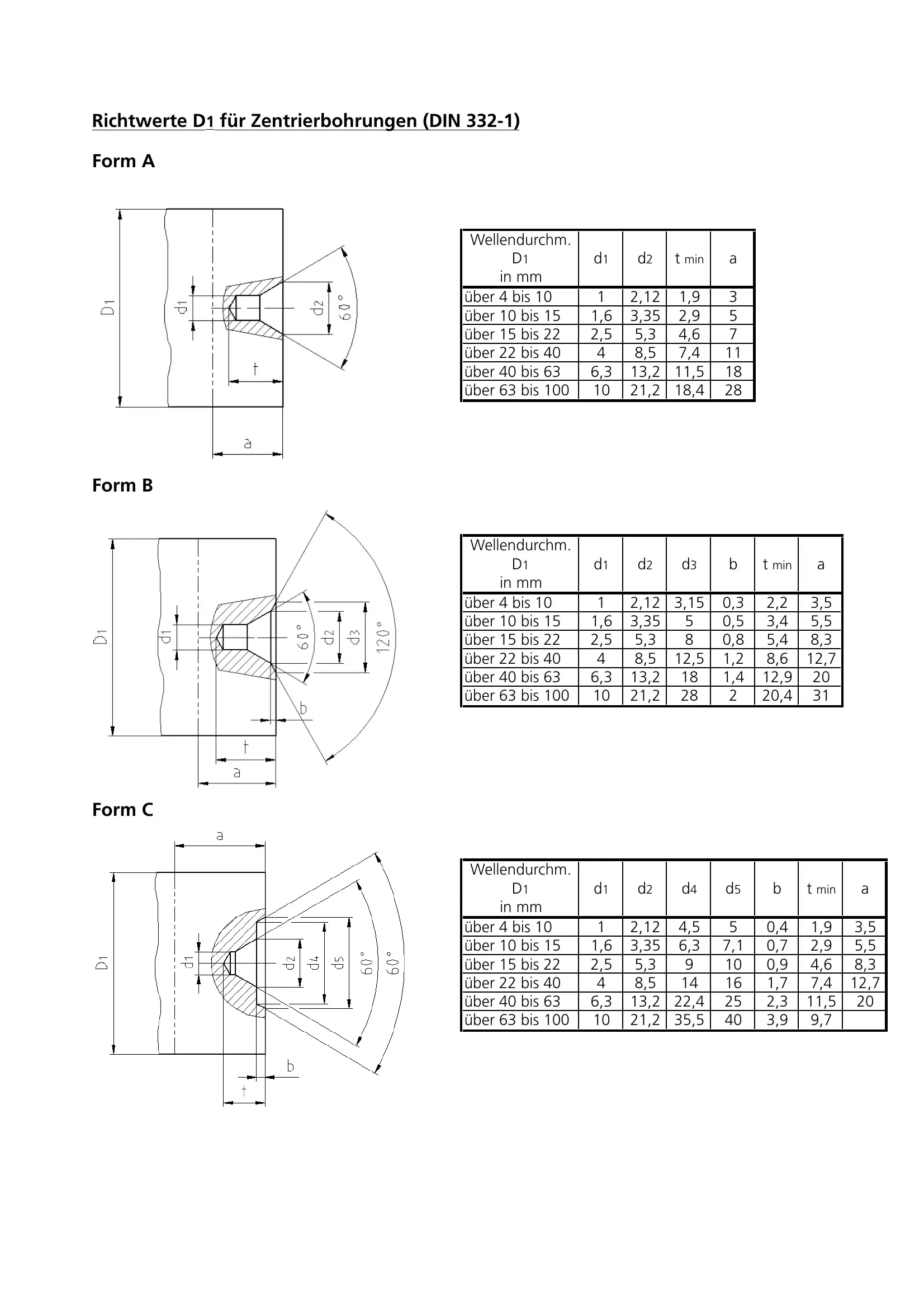
The DIN 332 form plays a crucial role in the domain of engineering and manufacturing, laying down the standard specifics for centering holes. This detail-oriented document categorizes centering holes into three distinct forms - A, B, and C, each tailored for different requirements and dimensions necessary in various applications. Form A outlines specifications for simple centering holes with dimensions ranging over shaft diameters from over 4mm to 100mm, providing values for drill sizes and minimum depths. In parallel, Form B expands on this by incorporating additional dimensions to cater for more complex needs, meeting the demands of projects that require precision and detail, especially over similar shaft diameters. Form C further extends these specifications by including even more intricate measurements for the most demanding of applications, ensuring that all possible requirements are covered. Each category is designed with precision, focusing on diameters, depths, and drill sizes to facilitate flawless execution in manufacturing processes. This standard underscores the importance of precision in engineering, offering a comprehensive guide that ensures compatibility, reliability, and quality in the production of centering holes.
| Question | Answer |
|---|---|
| Form Name | Din 332 Form |
| Form Length | 1 pages |
| Fillable? | No |
| Fillable fields | 0 |
| Avg. time to fill out | 15 sec |
| Other names | din 332 form d pdf, din 332 1, din 332 dr, din 332 2 pdf |
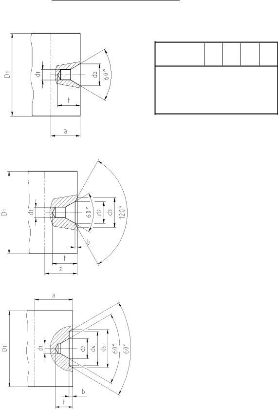
Richtwerte D1 fŸr Zentrierbohrungen (DIN
Wellendurchm.
D1 in mm
d1
d2
tmin
a
Ÿber 4 bis 10 |
1 |
2,12 |
1,9 |
3 |
Ÿber 10 bis 15 |
1,6 |
3,35 |
2,9 |
5 |
Ÿber 15 bis 22 |
2,5 |
5,3 |
4,6 |
7 |
Ÿber 22 bis 40 |
4 |
8,5 |
7,4 |
11 |
Ÿber 40 bis 63 |
6,3 |
13,2 |
11,5 |
18 |
Ÿber 63 bis 100 |
10 |
21,2 |
18,4 |
28 |
Form B
Wellendurchm. |
|
|
|
|
|
|
D1 |
d1 |
d2 |
d3 |
b |
t min |
a |
in mm |
|
|
|
|
|
|
Ÿber 4 bis 10 |
1 |
2,12 |
3,15 |
0,3 |
2,2 |
3,5 |
Ÿber 10 bis 15 |
1,6 |
3,35 |
5 |
0,5 |
3,4 |
5,5 |
Ÿber 15 bis 22 |
2,5 |
5,3 |
8 |
0,8 |
5,4 |
8,3 |
Ÿber 22 bis 40 |
4 |
8,5 |
12,5 |
1,2 |
8,6 |
12,7 |
Ÿber 40 bis 63 |
6,3 |
13,2 |
18 |
1,4 |
12,9 |
20 |
Ÿber 63 bis 100 |
10 |
21,2 |
28 |
2 |
20,4 |
31 |
Form C
Wellendurchm. |
|
|
|
|
|
|
|
D1 |
d1 |
d2 |
d4 |
d5 |
b |
t min |
a |
in mm |
|
|
|
|
|
|
|
Ÿber 4 bis 10 |
1 |
2,12 |
4,5 |
5 |
0,4 |
1,9 |
3,5 |
Ÿber 10 bis 15 |
1,6 |
3,35 |
6,3 |
7,1 |
0,7 |
2,9 |
5,5 |
Ÿber 15 bis 22 |
2,5 |
5,3 |
9 |
10 |
0,9 |
4,6 |
8,3 |
Ÿber 22 bis 40 |
4 |
8,5 |
14 |
16 |
1,7 |
7,4 |
12,7 |
Ÿber 40 bis 63 |
6,3 |
13,2 |
22,4 |
25 |
2,3 |
11,5 |
20 |
Ÿber 63 bis 100 |
10 |
21,2 |
35,5 |
40 |
3,9 |
9,7 |
|
|
|
|
|
|
|
|
|