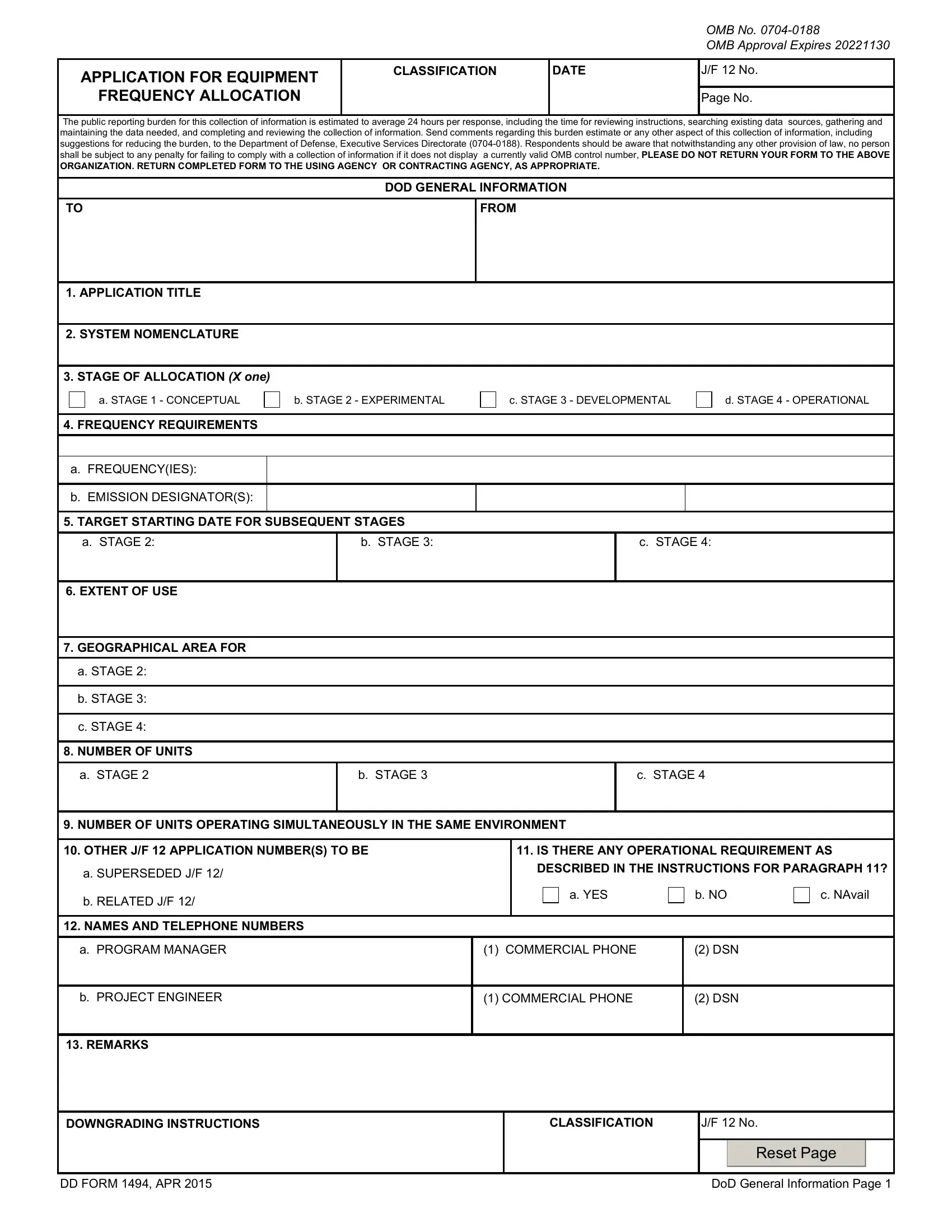
The DD Form 1494, "Application for Equipment Frequency Allocation," plays a critical role in the management and allocation of frequencies for various military and government-operated equipment. This form encompasses a wide array of technical specifications that need to be carefully completed to ensure the proper functioning and regulatory compliance of receiver equipment. It covers detailed information such as nomenclature, manufacturer's details, the type of receiver, its tuning range, and method of tuning, among others. The form also dives into the specifics of RF channeling capability, emission designators, frequency tolerance, and both IF and RF selectivity. Moreover, it includes data on de-emphasis, image rejection, and spurious rejection, providing a comprehensive overview of the equipment's capabilities. Such detailed technical benchmarks are essential for ensuring that the equipment does not interfere with existing frequency allocations and operates within its designated parameters. Completing the DD Form 1494 accurately is a meticulous process that requires a deep understanding of the equipment's characteristics and the regulatory environment governing frequency allocations. This form not only ensures the efficient use of the electromagnetic spectrum but also aids in maintaining the integrity of communication systems critical to national security and operational effectiveness.
| Question | Answer |
|---|---|
| Form Name | Dd Form 1494 |
| Form Length | 14 pages |
| Fillable? | No |
| Fillable fields | 0 |
| Avg. time to fill out | 3 min 30 sec |
| Other names | dd1494 3 dd form 1494 fillable |

CLASSIFICATION
PAGE
RECEIVER EQUIPMENT CHARACTERISTICS
1. NOMENCLATURE, MANUFACTURER’S MODEL NO. |
|
|
2. MANUFACTURER’S NAME |
|
|
|
|||||||||
|
|
|
|
|
|
|
|
|
|
|
|
|
|
|
|
3. RECEIVER INSTALLATION |
|
|
|
|
|
|
|
|
4. RECEIVER TYPE |
|
|
|
|||
|
|
|
|
|
|
|
|
|
|
|
|
|
|
|
|
5. TUNING RANGE |
|
|
|
|
|
|
|
|
6. METHOD OF TUNING |
|
|
|
|||
|
|
|
|
|
|
|
|
|
|
|
|
|
|
|
|
7. RF CHANNELING CAPABILITY |
|
|
|
|
|
|
|
8. EMISSION DESIGNATOR(S) |
|
|
|
||||
|
|
|
|
|
|
|
|
|
|
|
|
|
|
|
|
9. FREQUENCY TOLERANCE |
|
|
|
|
|
|
|
|
|
|
|
|
|
||
|
|
|
|
|
|
|
|
|
|
|
|
|
|||
10. IF SELECTIVITY |
|
1ST |
|
|
|
2ND |
|
3RD |
11. RF SELECTIVITY (X and complete as applicable) |
||||||
|
|
|
|
|
|
|
|
|
|
|
|
|
|
|
|
a. |
|
|
|
|
|
|
|
|
|
|
CALCULATED |
|
MEASURED |
||
|
|
|
|
|
|
|
|
|
|
|
|
|
|
||
|
|
|
|
|
|
|
|
|
|
|
|
|
|||
|
|
|
|
|
|
|
|
|
|
|
|
|
|
|
|
b. |
|
|
|
|
|
|
|
|
|
a. |
|
|
|
||
|
|
|
|
|
|
|
|
|
|
|
|
|
|
||
|
|
|
|
|
|
|
|
b. |
|
|
|
||||
|
|
|
|
|
|
|
|
|
|
|
|
|
|
||
|
|
|
|
|
|
|
|
|
|
|
|
|
|
|
|
c. |
|
|
|
|
|
|
|
|
|
c. |
|
|
|
||
|
|
|
|
|
|
|
|
|
|
|
|
|
|
||
|
|
|
|
|
|
|
|
d. PRESELECTION TYPE |
|
|
|
||||
|
|
|
|
|
|
|
|
|
|
|
|
|
|
||
|
|
|
|
|
|
|
|
|
|
|
|
|
|
|
|
12. IF FREQUENCY |
|
|
|
|
|
|
|
|
|
|
|
|
|
||
|
|
|
|
|
|
|
|
|
|
|
|
|
|
||
a. 1ST |
|
|
|
|
|
|
|
|
13. MAXIMUM POST DETECTION FREQUENCY |
||||||
|
|
|
|
|
|
|
|
|
|
|
|
|
|||
|
|
|
|
|
|
|
|
|
|
|
|
|
|
|
|
b. 2ND |
|
|
|
|
|
|
|
|
|
|
|
|
|
||
|
|
|
|
|
|
|
|
14. MINIMUM POST DETECTION FREQUENCY |
|||||||
|
|
|
|
|
|
|
|
|
|
|
|||||
|
|
|
|
|
|
|
|
|
|
|
|
|
|
|
|
c. 3RD |
|
|
|
|
|
|
|
|
|
|
|
|
|
||
|
|
|
|
|
|
|
|
|
|
|
|||||
15. OSCILLATOR TUNED |
|
1ST |
|
2ND |
|
3RD |
16. MAXIMUM BIT RATE |
|
|
|
|||||
|
|
|
|
|
|
|
|
|
|
|
|
|
|
||
a. ABOVE TUNED |
|
|
|
|
|
|
|
|
|
|
|
|
|
||
|
FREQUENCY |
|
|
|
|
|
|
|
|
17. SENSITIVITY |
|
|
|
||
|
|
|
|
|
|
|
|
|
|
|
|
|
|
||
b. BELOW TUNED |
|
|
|
|
|
|
|
|
a. SENSITIVITY |
|
|
dBm |
|||
|
FREQUENCY |
|
|
|
|
|
|
|
|
|
|
||||
|
|
|
|
|
|
|
|
|
|
|
|
|
|
||
|
|
|
|
|
|
|
|
|
|
|
|
|
|
||
c. EITHER ABOVE OR BELOW |
|
|
|
|
|
|
|
|
b. CRITERIA |
|
|
|
|||
|
TUNED FREQUENCY |
|
|
|
|
|
|
|
|
|
|
|
|||
|
|
|
|
|
|
|
|
|
|
|
|
|
|
||
|
|
|
|
|
|
|
|
|
|
|
|
|
|
||
18. |
|
|
|
|
|
|
|
|
c. NOISE FIG |
|
|
dB |
|||
|
a. YES |
|
|
|
|
b. NO |
|
|
|
|
|||||
|
|
|
|
|
|
|
|
|
|
|
|
||||
|
|
|
|
|
|
|
d. NOISE TEMP |
|
|
Kelvin |
|||||
|
|
|
|
|
|
|
|
|
|
|
|
|
|||
|
|
|
|
|
|
|
|
|
|
|
|
||||
|
|
|
|
|
|
|
|
|
|
|
|
|
|||
19. IMAGE REJECTION |
|
|
|
|
|
|
|
|
20. SPURIOUS REJECTION |
|
|
|
|||
|
|
|
|
|
|
|
|
|
|
|
|
|
|
||
21. REMARKS |
|
|
|
|
|
|
|
|
|
|
|
|
|
||
|
|
|
|
|
|
|
|
|
|
|
|
|
|
|
|
CLASSIFICATION
DD FORM 1494, AUG 96

INSTRUCTIONS FOR COMPLETING DD FORM 1494,
"APPLICATION FOR EQUIPMENT FREQUENCY ALLOCATION"
RECEIVER EQUIPMENT CHARACTERISTICS PAGE
ITEM 1 - Nomenclature, Manufacturer’s Model No. Enter the Government assigned alphanumeric equipment designation. If above is not available, enter the manufacturer’s model number, e.g., MIT 502, and complete Item 2. If above is not available, enter a short descriptive title, e.g., GPS Receiver, Director Station RX.
ITEM 2 - Manufacturer’s Name. Enter the manufacturer’s name if available. If a manufacturer’s model number is listed in Item 1, this item must be completed.
ITEM 3 - Receiver Installation. List specific type(s) of vehicle(s), ship(s), plane(s) or building(s), etc., where the receiver(s) will be installed.
ITEM 4 - Receiver Type. Enter the generic class, e.g., Dual Conversion Superheterodyne or Homodyne.
ITEM 5 - Tuning Range. Enter the frequency range through which the receiver is capable of being tuned, e.g.,
ITEM 6 - Method of Tuning. Enter the method of tuning, e.g., crystal, synthesizer or cavity. If the equipment is not readily tunable in the field, indicate in Item 21, "Remarks," the complexity of tuning. Include complexity factors such as skill levels involved, major assemblies involved, time required, and location (factory or depot) where equipment is to be tuned.
ITEM 7 - RF Channeling Capability. Describe the RF channeling capability. For uniformly spaced channels, enter the center frequency of the first channel and channel spacing e.g., first channel 406 MHz, 100 kHz increments; for continuous tuning, enter the lowest frequency and the word "continuous;" for others, including cases where channel selection is under software control, enter a detailed description in Item 21, "Remarks."
ITEM 8 - Emission Designator(s). Enter the emission designator(s) including the necessary bandwidth(s) for each designator, e.g., 16K0F3E. For systems with a frequency hopping mode as well as a
ITEM 9 - Frequency Tolerance. Enter the frequency tolerance, i.e., the maximum departure of a receiver from its assigned frequency after normal
ITEM 10 - IF Selectivity. Enter the bandwidth for each IF stage at the
ITEM 11 - RF Selectivity. Enter the bandwidth at the
ITEM 12 - IF Frequency. Enter the tuned frequency of the first, second and third IF stages. Indicate units, e.g., kHz or MHz.
ITEM 13 - Maximum Post Detection Frequency. Enter the maximum post detection frequency. This is the nominal frequency at the
ITEM 14 - Minimum Post Detection Frequency. For multichannel FM systems enter the minimum post detection frequency. This is the nominal frequency at the
ITEM 15 - Oscillator Tuned. Mark the appropriate block to indicate the location of the 1st, 2nd and 3rd oscillator frequencies with respect to the associated mixer input signal.
ITEM 16 - Maximum Bit Rate. Where applicable, enter the maximum bit rate (bps) that can be used. If spread spectrum is used, enter the bit rate after encoding. Describe any error detecting/correcting codes in Item 21, "Remarks."
ITEM 17 - Sensitivity.
a.Enter the sensitivity in dBm.
b.Specify criteria used, e.g., 12 dB SINAD (Signal to Interference plus Noise and Distortion).
c.If the receiver is used with terrestrial systems, enter the receiver noise figure in dB.
d.If the receiver is used with space or satellite earth stations, enter the receiver noise temperature in Kelvin.
ITEM 18 -
ITEM 19 - Image Rejection. Enter the image rejection in dB. Image rejection is the ratio of the image frequency signal level required to produce a specified output, to the desired signal level required to produce the same output.
ITEM 20 - Spurious Rejection. Enter the spurious rejection in dB. Enter the single level of spurious rejection that the receiver meets or exceeds at all frequencies outside the
DD FORM 1494, AUG 96 |
Receiver Equipment Characteristics Page (Back) |