
 Received by
 Valuation
 IWC
IWC ft
ft IWX / 100’
 Fax
Fax 
 Lot #
Lot # 
 ft
ft
 btu
btu btu
btu ft
ft ft
ft in
in in
in btu
btu btu
btu ft
ft ft
ft in
in in
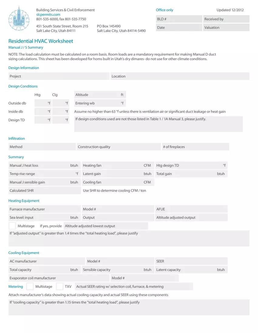
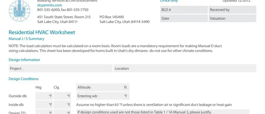
inCreating forms using this PDF editor is simpler in comparison with anything else. To edit blank manual j forms the document, there isn't anything you should do - simply proceed with the steps below:
Step 1: Search for the button "Get Form Here" and hit it.
Step 2: Now you are on the file editing page. You can modify and add text to the document, highlight words and phrases, cross or check specific words, include images, put a signature on it, erase unnecessary fields, or eliminate them completely.
The following areas will make up your PDF file:
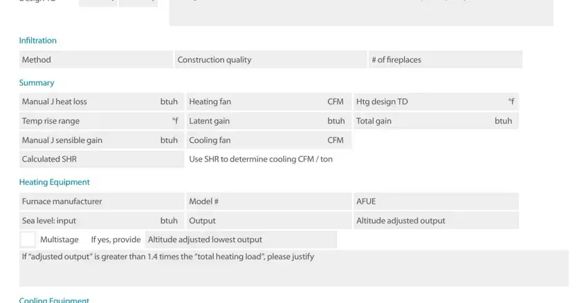
Fill out the Design TD, If design conditions used are not, Infiltration, Method, Summary, Construction quality, of fireplaces, Manual J heat loss, btuh, Heating fan, CFM, Htg design TD, Temp rise range, Latent gain, and btuh section with the particulars asked by the system.
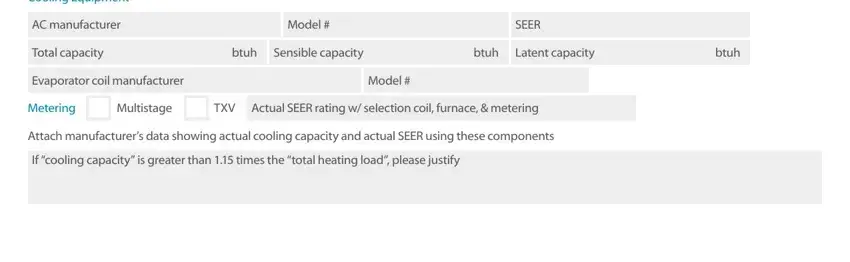
Note all details you need inside the box Cooling Equipment, AC manufacturer, Total capacity, Model, SEER, btuh, Sensible capacity, btuh, Latent capacity, btuh, Evaporator coil manufacturer, Model, Metering, Multistage, and TXV.
The Manual D Calculations Summary, Project, Friction Rate Worksheet Steps, Manufacturers Blower Data, External static pressure ESP, IWC, CFM, Device Pressure Losses, Evaporator, Air filter, Available Static Pressure ASP, ASP ESP DPL, IWC, Supply register, and Other device section is the place to indicate the rights and responsibilities of both parties.
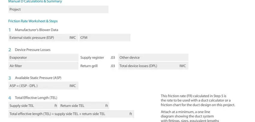
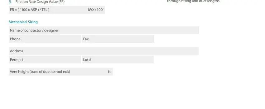
Look at the areas Attach at a minimum a one line, Friction Rate Design Value FR, FR x ASP TEL, IWX, Mechanical Sizing, Name of contractor designer, Phone, Address, Permit, Fax, Lot, and Vent height base of duct to roof and then fill them in.
Step 3: Once you select the Done button, your finalized document can be simply exported to each of your gadgets or to electronic mail chosen by you.
Step 4: To protect yourself from any sort of concerns later on, be sure to get as a minimum several copies of your file.
